Method and apparatus for integrating on-shore green and other on-shore power sources with a compressed air energy storage system on a floating power plant.

a technology of compressed air and power source, which is applied in the direction of wind power with solar radiation, electric generator control, greenhouse gas reduction, etc., can solve the problems of increasing the cost of power for many islands and isolated locations, increasing the cost of power storage, so as to reduce the fuel consumption of nearby turbocompressor driven gensets and high mass flow. , the effect of high mass flow

Inactive Publication Date: 2014-11-13
ENIS +1
View PDF2 Cites 16 Cited by
  • Summary
  • Abstract
  • Description
  • Claims
  • Application Information

AI Technical Summary

Benefits of technology

[0109]Not only does the Enis / Lieberman CAES system versus the cavern system avoid burning fuel in its generation of electricity but also has high mass flow of super-chilled air output that reduces the fuel consumption of nearby turbocompressor driven Gensets.
[0110]The isolated locations of these islands also have greater use of refrigeration facilities for their fish processing and storage facilities. The high mass flow of superchilled air from the turboexpander exhaust is of immediate use in that scenario. This all-fresh-air configuration avoids the need for the typical ammonia refrigeration facilities that have a history of toxic plume release as the ammonia storage tanks age.
[0111]In summary, the integration of the FPP and Enis / Lieberman CAES system creates a portable (shippable) facility for delivering electric power and high mass flow of super-chilled air to remote locations in a short installation time and with reduced need for fuel combustion. There is also the potential to introduce desalination as a step in the overall process. Payback periods in isolated areas where energy cost rates are high will result in payback periods less than 3 years. It is the integration of the cost of the barge construction and the pressure vessel construction that permits these advantages.

Problems solved by technology

One of the factors limiting the Enis / Lieberman version of the Compressed Air Energy Storage (CAES) system is the payback period after the system installation.
The major contributing factor is the cost of the thick steel wall pressure vessels required for the energy storage.
Also the fundamental cost of power for many of the island and isolated locations is about three-fold more expensive than populated areas so that payback periods are further shortened.
The deep underground cavern CAES systems not only are geographically and geologically limited but they have long study periods and long installation periods associated with 5 to 10 years.

Method used


Image

  • Method and apparatus for integrating on-shore green and other on-shore power sources with a compressed air energy storage system on a floating power plant.
  • Method and apparatus for integrating on-shore green and other on-shore power sources with a compressed air energy storage system on a floating power plant.
  • Method and apparatus for integrating on-shore green and other on-shore power sources with a compressed air energy storage system on a floating power plant.

Examples


Embodiment Construction

[0128]The following discussion contains a narrative of the invention that integrates the CAES system and its variations with the FPP system. The narrative is followed by a calculation that sizes a specific system as an example.

a. Narrative

[0129]The electric utility supply power system is comprised of (1) Transportable Compressed Air Energy Storage (T-CAES) system and its specific versions described herein and (2) Floating Power Plant (FPP) barge.

[0130]1. Transportable Compressed Air Energy Storage (T-CAES) System

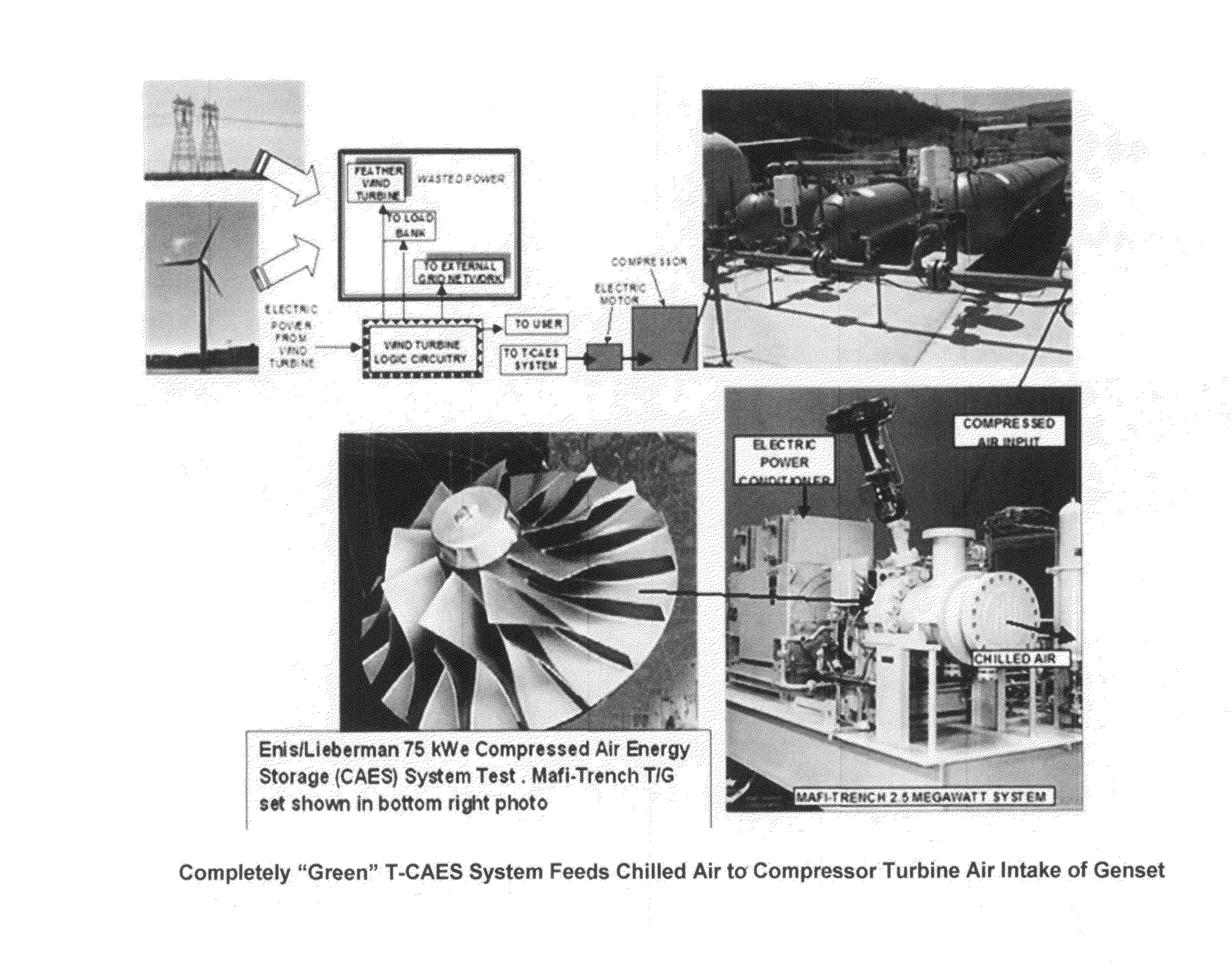
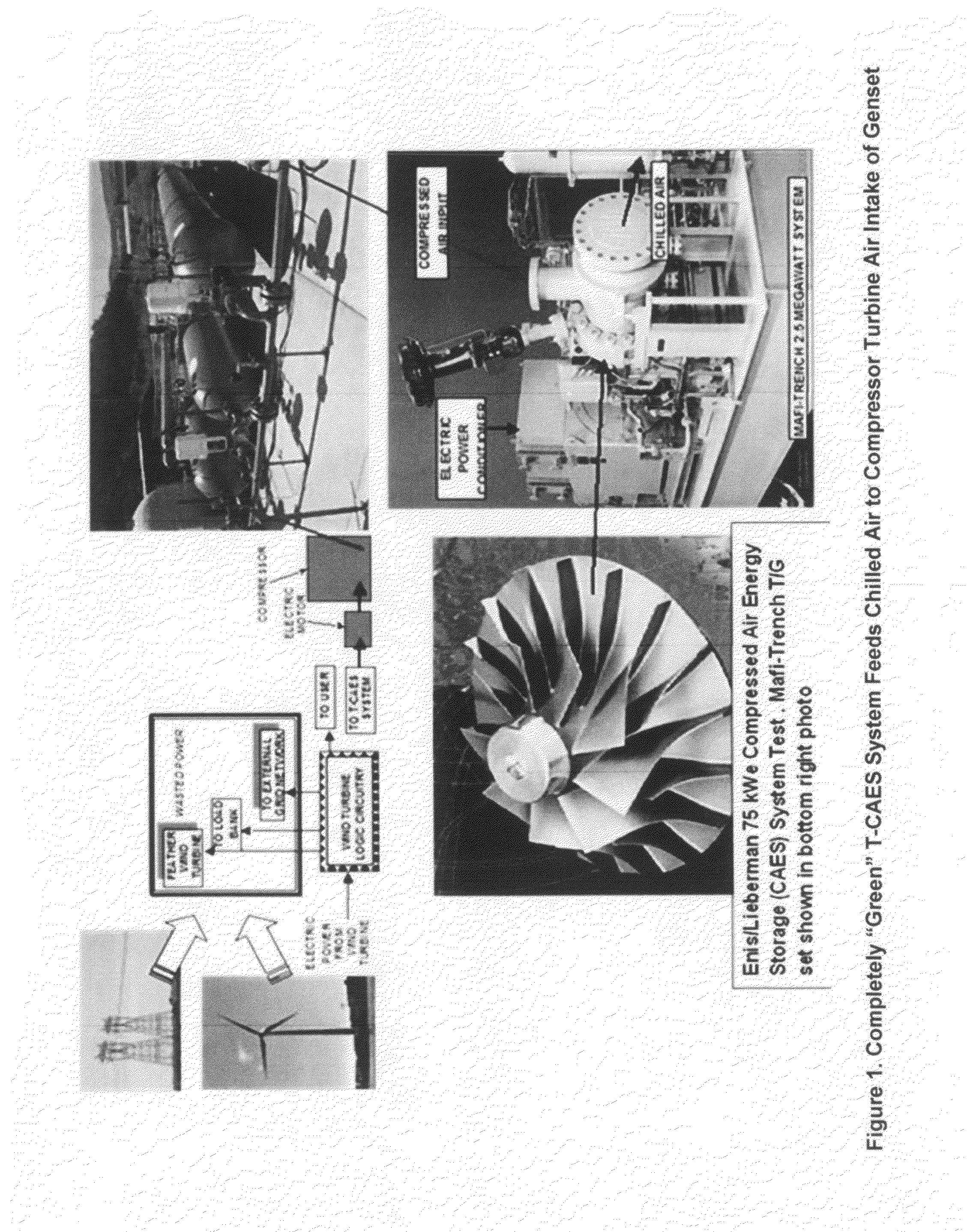
[0131]FIG. 1 describes the Enis / Lieberman Compressed Air Energy Storage (CAES) system that uses either commercial power from the grid when the T-O-U schedule is to our advantage or uses green power to drive a multistage air compressor to pressurize the air in the pressure vessel wherein the energy is stored for later usage. When the energy is needed, the air mass control valve releases the pressure in the pressure vessel and feeds the steady high mass of near room temperatur...


PUM


Abstract

The invention relates to a method and apparatus that shares the cost and areal footprint of the barge floatation platform for a floating power platform (FPP) with the cost and aerial footprint of the high pressure vessels of the compressed air energy storage (CAES) system. The integration of these two systems provides cost savings and energy consumption savings with potential for desalination.

Description

RELATED PATENT AND PENDING PATENTS[0001]Enis B. and Lieberman P., TITLE: “Method and Apparatus for Using Wind Energy or Solar Energy for an Underwater and / or for an Under Seabed Compressed Air Energy Storage System”[0002]1. Application Ser. No. 13 / 610,440, ISSUE DATE Sep. 11, 2012[0003]Enis B. and Lieberman P., TITLE: “Wind Turbine Station and Tower with Vertical Storage Tanks”[0004]1. U.S. PROVISIONAL PATENT APPLICATION—PENDING[0005]Enis B. and Lieberman P., TITLE: “Method and Apparatus for Using Wind Turbines to Generate and Supply Uninterrupted Power to Locations Remote from the Power Grid”[0006]1. U.S. Pat. No. 6,927,503, ISSUE DATE: Aug. 9, 2005[0007]2. U.S. Pat. No. 7,067,937, ISSUE DATE Jun. 27, 2006[0008]3. U.S. Pat. No. 7,250,691, ISSUE DATE Jul. 31, 2007[0009]Enis B. and Lieberman P., TITLE: “A Method of Coordinating and Stabilizing the Delivery of Wind Generated Energy”[0010]1. U.S. Pat. No. 6,963,802, ISSUE DATE: Nov. 8, 2005[0011]2. U.S. Pat. No. 7,308,361 B2, ISSUE DAT...

Claims


Application Information

Patent Timeline
Patent Type & Authority Applications(United States)
IPC IPC(8): H02K7/18
CPCH02K7/1823B63B2035/4433H02S10/20H02S10/12H02J3/381Y02E20/14F03D9/17Y02E70/30Y02A20/142Y02A20/141F02C6/16H02J2300/40H02J2310/10H02J2300/10H02J2300/28H02J2300/20H02J2300/24Y02E10/56Y02E10/76Y02E10/72Y02E60/16F03D9/007
Inventor LIEBERMAN, PAUL
Owner ENIS
Why Eureka
Try Eureka