Aircraft using turbo-electric hybrid propulsion system for multi-mode operation

a hybrid propulsion system and aircraft technology, applied in the direction of sustainable transportation, transportation and packaging, energy-saving board measures, etc., can solve the problems of helicopters exceedingly vulnerable to infrared (ir) seeking weaponry attacks, significant drawbacks of conventional gas turbine-based propulsion systems for certain types, etc., to achieve convenient turning in a preferred direction, improve aircraft maneuverability, and adapt quickly

Inactive Publication Date: 2014-11-27
SALYER IVAL O
View PDF6 Cites 107 Cited by
  • Summary
  • Abstract
  • Description
  • Claims
  • Application Information

AI Technical Summary

Benefits of technology

[0008]A controller may be used to provide some automation to the operation of the aircraft. Included is the ability to vary operation of the aircraft between a first and second portion of its flight envelope. In a more particular form, the controller can be used in conjunction with actuation equipment to provide full robotic control of the aircraft over many or all segments of the aircraft flight envelope, including take-off and landing. Such full control is especially beneficial in unmanned aircraft configurations. Suitable controllers and ancillary equipment (such as actuators, transceivers and related communication infrastructure, electric wiring, sensors or the like) may enable the aircraft to be readily adaptive for computer control and robotic (i.e., unmanned air vehicles (UAVs)) or other remote flying. The controller may also be used to provide differing control signals to each of the outboard gas turbine engines such that improved aircraft maneuverability is possible through steering, turning or the like. In one form, the controller may include four throttle control for each of the two gas turbine engines or to each of the two single bladed rotors to be separately controlled. For example, by decreasing the power to the port or starboard rotor and increasing to the opposing starboard or port rotor, turning in a preferred direction may be facilitated. Likewise, the thrust from the engines can also be varied wherein the power to the engine on one side of the fuselage or the other can be decreased while the opposing engine's power is increased when turning.

Problems solved by technology

Despite their widespread use, conventional gas turbine-based propulsion systems have significant drawbacks for certain types of aircraft.
For example, in the event a turboshaft engine fails, a helicopter, gyrocopter or other inherently unstable aircraft has no way of returning to earth under its own power, and at best can expect to have to endure a controlled crash landing.
Likewise, if a helicopter employing a turboshaft engine as propulsive power is flying or hovering over an area where terrorists, armed conflict or related hostilities exist, the extreme heat put out by the engine or engines may make the helicopter exceedingly vulnerable to attack from infrared (IR) seeking weaponry.
Furthermore, to the extent that there are existing rotary-winged aircraft (such as the Bell Boeing V-22 Osprey) that are configured to operate in both a helicopter mode of operation and in a fixed-wing aircraft mode of operation, significant mechanical complications abound, including the necessity of tilting the entire wing in order to shift between modes.
Moreover, such a configuration does not provide the ability to operate as a gyrocopter, where additional fuel economy and related range may be possible.
In addition, in situations where power may be lost, there is no ability with a design where the propeller is directly coupled to the engine to shift the rotors into a freewheeling position; this in turn imperils slow, controlled aircraft descents for emergency landings.

Method used


Image

  • Aircraft using turbo-electric hybrid propulsion system for multi-mode operation
  • Aircraft using turbo-electric hybrid propulsion system for multi-mode operation
  • Aircraft using turbo-electric hybrid propulsion system for multi-mode operation

Examples


Embodiment Construction

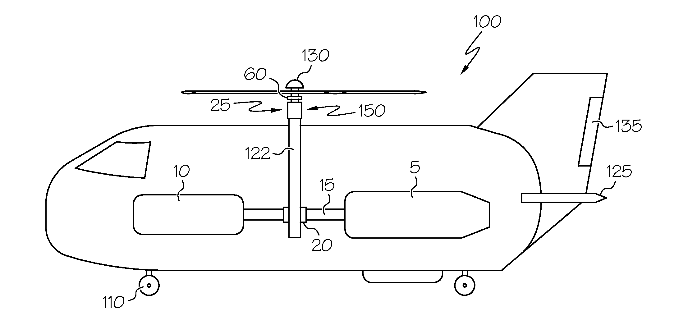
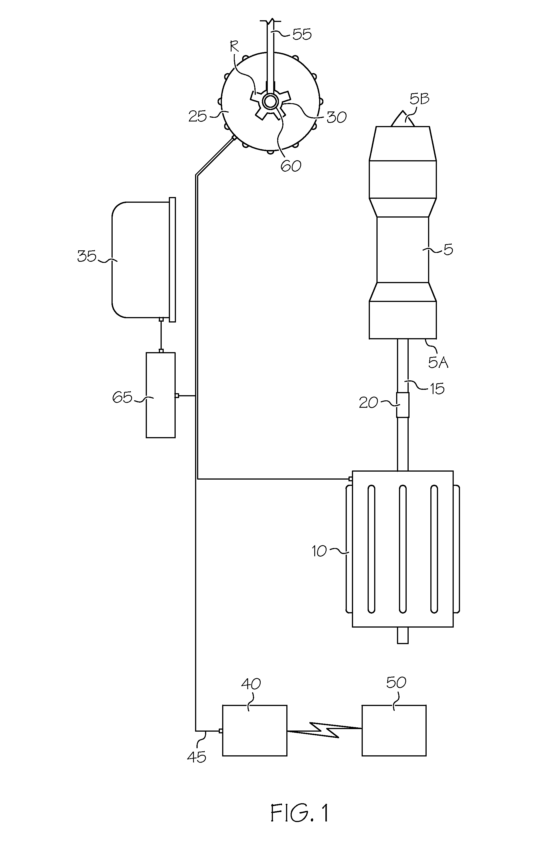
[0016]Referring initially to FIG. 1, a hybrid propulsion system 1 according to an embodiment of the present invention is shown. In the present context, a hybrid propulsion system is one that provides motive power for an aircraft or other vehicle from two or more disparate power sources. In a more particular form, the hybrid propulsion system 1 is a turbo-electric propulsion system that is particularly well-suited to powering a rotary-winged aircraft such as a helicopter or autogyro, as well as a fixed-wing aircraft that will be discussed in more detail below. The invention disclosed herein achieves that objective through shaft power provided by an internal combustion engine and electric power provided by one or more batteries. Both power sources, which are described below in more detail, can convert their energy into a form useable by an electric motor that can be used to turn one or more lifting surfaces on an aircraft, as well as one or more propulsive members in a watercraft or l...


PUM


Abstract

A vehicle incorporating a hybrid propulsion system. In one form, the vehicle may be an aircraft such that the system includes gas turbine engines as a first motive power source, and one or more battery packs as a second motive power source. Through selective coupling to an electric motor that can in turn be connected to a bladed rotor or other lift-producing device, the motive sources provide differing ways in which an aircraft can operate. In one example, the gas turbine engines can provide operation for a majority of the flight envelope of the aircraft, while the battery packs can provide operation during such times when gas turbine-based motive power is unavailable or particularly disadvantageous. In another example, both sources of motive power may be decoupled from the bladed rotor such that the vehicle can operate as an autogyro. In another mode of operation, the movement of a bladed rotor can be both decoupled from the sources of propulsion as well as fixed relative to the aircraft such that the aerodynamic surfaces formed on the bladed rotors can act as a fixed wing. In another particular form, the vehicle may be ground-based or water-based.

Description

BACKGROUND OF THE INVENTION[0001]The present invention relates generally to vehicles with hybrid propulsion systems, and more particularly to a combination of a gas turbine-based propulsion system and a stored electric-based power system that cooperates with rotational lift or thrust-producing devices to permit a vehicle to operate in numerous modes of movement.[0002]Aircraft are broadly categorized as either fixed-wing vehicles (such as an airplane) or rotary-wing vehicles (such as helicopters and autogyros, the latter also referred to as autogyros or gyrocopters). Gas turbine engines (which are one form of internal combustion engine) are widely used to power both the fixed-wing and rotary wing forms of aircraft, where fixed-wing vehicles often employ turbofan, turbojet and turboprop variants, and rotary-wing vehicles often employ turboshaft variants. In all circumstances, the basic gas generator hardware is common, including a compressor, a combustor and turbine, where the compres...

Claims


Application Information

Patent Timeline
Patent Type & Authority Applications(United States)
IPC IPC(8): B64C37/00B64D27/24B64D27/14
CPCB64C37/00B64D27/14B64D2027/026Y10S903/903B64D27/24B64C27/14B64C27/24Y02T50/40Y02T50/50Y02T50/60
Inventor SALYER, IVAL O.
Owner SALYER IVAL O
Why Eureka
Try Eureka