Method of generating hydrogen

a hydrogen and hydrogen technology, applied in the field of hydrogen generation, can solve the problems of short reaction time, insufficient hydrogen generation, and insufficient purification water, and achieve the effects of long life span, long reaction time, and large reaction surface area

Inactive Publication Date: 2014-12-11
ISHIKAWA YASUO
View PDF5 Cites 9 Cited by
  • Summary
  • Abstract
  • Description
  • Claims
  • Application Information

AI Technical Summary

Benefits of technology

[0036]The Molten salt of this invention as catalyst comprises alkaline metal hydroxide such as NaOH and KOH or alkaline earth metal hydroxide such as Ba(OH)2 and Sr(OH)2, a first metal element (Ni, Pd or Pt) for cutting the combination of hydrogen and oxygen and a second metal element (Cr, Mo, W, Fe, Co, Cu or Rh) for helping the function of the first metal element. The mixture of the hydroxide and the first and second metal elements is heated at a temperature above the melting point of the hydroxide to separate hydrogen from oxygen. That is, the catalyst can operate at a temperature above 300° C. and, however, a continuous operation needs at approximately 500° C. The catalyst does not cause a simple oxidizing reaction but an electrical and chemical reaction or an ionizing reaction. In addition, a main reaction is caused by fine particles ejected from the liquid surface of the catalyst to enlarge remarkably a reaction surface area, and the life span of the catalyst is long (over 3 months). Further, much water can be divided into hydrogen and oxygen at a low temperature.
[0037]In the case of solid catalyst, a reaction for resolving water is the same as that of the liquid catalyst, its reaction temperature is slightly higher than that of liquid catalyst. It is preferable to use solid catalyst in case that a catalyst unit is swung in ships and automobiles.
[0038]In the method of generating hydrogen according to this invention, molten salt itself is ionized together with a metal element for cutting the combination of hydrogen, and there are a lot of electrons in the molten salt. Therefore, the fine particles dispersed from the liquid surface react on steam to ionize it thereby to produce a lot of hydrogen at a low temperature because of a remarkable largeness of reaction surface area. In addition, oxygen separated from hydrogen makes oxide, a part of which can make up for the catalyst after reacting on steam and its remains flow out. Therefore, the catalyst cell is not full of oxide to extend the life span of the catalyst.
[0039]In the apparatus for generating hydrogen according to this invention, there are provided the catalyst cell having corrosion resistance, the steam producing portion, the metal element supply body including the case of the catalyst cell, the heating device for heating the catalyst, and the air inflow prevention device for preventing air from flowing into the catalyst cell, and, therefore, the catalyst can have a long life span with a simple structure. Further, since the steam producing portion is formed in the catalyst cell, the portion and the catalyst can be heated by a single heating device to make the structure of the apparatus simple. And if the catalyst cell itself has the same function as that of the metal element supply body, the fins are unnecessary.
[0040]A water tank as the steam elimination device has a function as the air inflow prevention device, and, therefore, the numbers of necessary members can be decreased.
[0041]Further, a vertical type of catalyst cell is, at its circumferential wall, heated by the plate-shaped heater, and, therefore, the reaction space formed at the upper portion of the catalyst cell can be effectively heated.

Problems solved by technology

In the above Patent Publication 1, the technology has a fault that pure water is necessary and long time is necessary to take hydrogen out of water because the furnace is heated gradually.
In the above Patent Publication 2, there is a fault that chelating agent is necessary and the amount of hydrogen generation is little.

Method used


Image

  • Method of generating hydrogen
  • Method of generating hydrogen
  • Method of generating hydrogen

Examples


experimental example

5) EXPERIMENTAL EXAMPLE

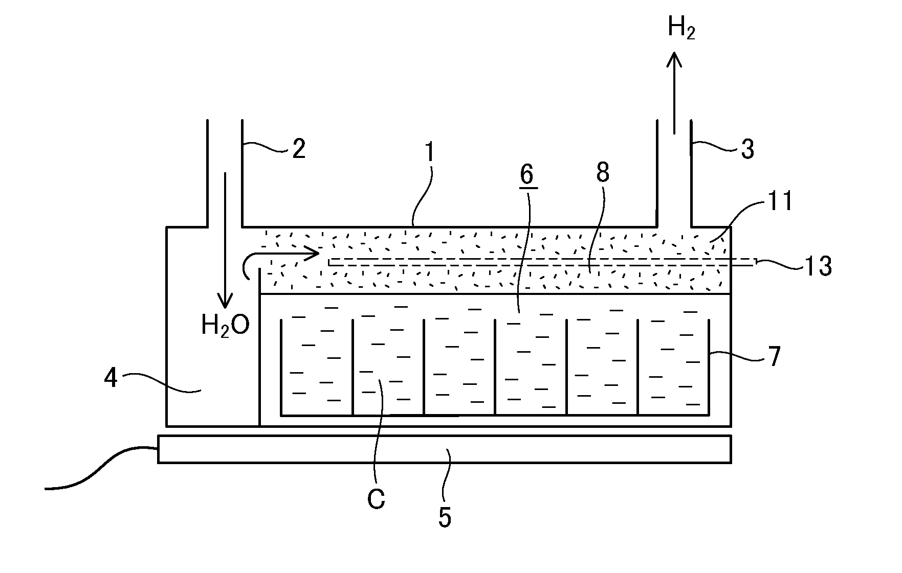
[0174]Next, experimental examples in which the hydrogen generating apparatus shown in FIG. 1 is used will now be explained. The existence of hydrogen was made sure by combustion tests of hydrogen.

1. The First Experimental Example

[0175]0.2 cc of water was supplied every 10 minutes into the casing 1 (width: 50 mm, length: 200 mm, height: 15 mm) without any catalyst therein. At this time, hydrogen is generated at a temperature of approximately 700° C., and however, the generation of hydrogen was stopped after 4 to 6 hours.

[0176]The material of the casing 1 was 18-8 stainless steel containing 18% Cr, 8% Ni and remains Fe.

[0177]In case that approximately 20 g of scrap stainless steel was put into the casing 1, hydrogen were generated for two days. Instead of the scrap stainless steel, scrap copper of approximately 10 g was put into the casing 1. At this time, the generation of hydrogen was stopped after one day. Further, when 96 g of scrap iron was input into the c...


PUM

PropertyMeasurementUnit
temperatureaaaaaaaaaa

Abstract

A catalyst has a long life span and efficiently separates hydrogen from water. A first metal element (Ni, Pd, Pt) for cutting the combination of hydrogen and oxygen and a second metal element (Cr, Mo, W, Fe) for helping the function of the first metal element are melted in alkaline metal hydroxide or alkaline earth metal hydroxide to make a mixture heated at a temperature above the melting point of the hydroxide to eject fine particles from the liquid surface, bringing steam into contact with the fine particles. Instead of this, a mixture of alkaline metal hydroxide and metal oxide is heated at a temperature above the melting point of the alkaline metal hydroxide to make metal compound in which at least two kinds of metal elements are melted, and fine particles are ejected from the surface of the metal compound to be brought into contact with steam.

Description

TECHNICAL FIELD[0001]This invention relates to catalyst for taking hydrogen out of water, a method of generating hydrogen by using the catalyst, and an apparatus for generating hydrogen by using the method.BACKGROUND OF THE INVENTION[0002]As a method of taking hydrogen out of water, there is known a method of heat-resolving pure water into hydrogen and oxygen through a catalyst (Japanese Laid Open Publication Hei10-212101). In this method, a silicon oxide as catalyst is put into a rotatable furnace to evacuate the inside of the furnace.[0003]After the evacuation, pure water is put into the furnace which is heated at a temperature of 350° C. to 700° C. gradually to generate hydrogen and oxygen.[0004]Further, there is known another method of generating hydrogen in which metal catalyst such as finely crushed platinum or palladium is brought into contact with water containing chelating agent kept at a temperature of approximately 60° C. to 150° C. (Japanese Laid Open Publication Sho 62-...

Claims


Application Information

Patent Timeline
Patent Type & Authority Applications(United States)
IPC IPC(8): C01B3/10
CPCC01B3/10C01B2203/0805C01B2203/0272C01B3/045Y02E60/36
Inventor ISHIKAWA, YASUO
Owner ISHIKAWA YASUO
Why Eureka
Try Eureka