Crosspolar multiband panel antenna

a multi-band panel antenna and cross-polar technology, applied in the field of telecom antennas, can solve the problems of increasing the coupling between the radiating elements operating, requiring a diversity of signals, and the implementation of decoupling techniques becoming increasingly complicated, so as to improve the decoupling effect, increase the size of the cross-polar multi-band panel antenna, and the effect of increasing the weight or cos

Inactive Publication Date: 2014-12-18
ALCATEL LUCENT SAS
View PDF15 Cites 30 Cited by
  • Summary
  • Abstract
  • Description
  • Claims
  • Application Information

AI Technical Summary

Benefits of technology

[0007]It is therefore a purpose of the present invention to improve decoupling between the two polarizations of the radiating elements of an antenna array operating within the same frequency band, without considerably increasing the size of a crosspolar multiband panel antenna, nor the weight or cost associated with it.
[0010]This is a new architecture of a crosspolar multiband panel antenna in which physical decoupling is combined with the traditionally used polarization decoupling, for each of the radiating elements, thereby allowing them to improve MIMO applications and applications that require diversity of signals.
[0017]According to one embodiment, all of the first polarizations belonging to one antenna array and all of the second polarizations belonging to the same antenna array are disposed with respect to one another in such a way as to increase the distance separating the first polarization from the second polarization of a single radiating element.
[0019]One advantage of the invention is to improve decoupling between the cross-polarization radiating elements of the antenna arrays composing a multiband panel antenna combining the spatial decoupling with the polarization decoupling for each radiating element in order to get better results for signal diversity algorithms and MIMO. It also makes it possible to simplify the design and overall internal structure of the crosspolar multiband panel antenna, without increasing the dimensions of the chassis, all while offering additional decoupling between the two polarizations owing to the distance physically separating them. It thereby makes it possible to increase decoupling between the polarizations for each frequency band (improved by 5-10 dB).

Problems solved by technology

However, within the increase in the number of frequency bands, and therefore in the number of antenna arrays within a single volume, such configurations lead to an increase in coupling between the radiating elements operating within each of those antenna arrays, which is a drawback in particular for MIMO applications and that requiring a diversity of signals.
Assuming a crosspolar multiband panel antenna comprising a plurality of antenna arrays (at least 2, and up to 5 or even more) having separate operating frequency bands, each made up of aligned radiating elements placed under a single radome and carried by the same reflector, it is understood that these decoupling techniques become increasingly complicated to implement, because there is not enough physical space available within the chassis' overall volume to be able to maintain the same general form factor as traditional panel antennas that operate in at least two distinct frequency bands.

Method used


Image

  • Crosspolar multiband panel antenna
  • Crosspolar multiband panel antenna
  • Crosspolar multiband panel antenna

Examples


Embodiment Construction

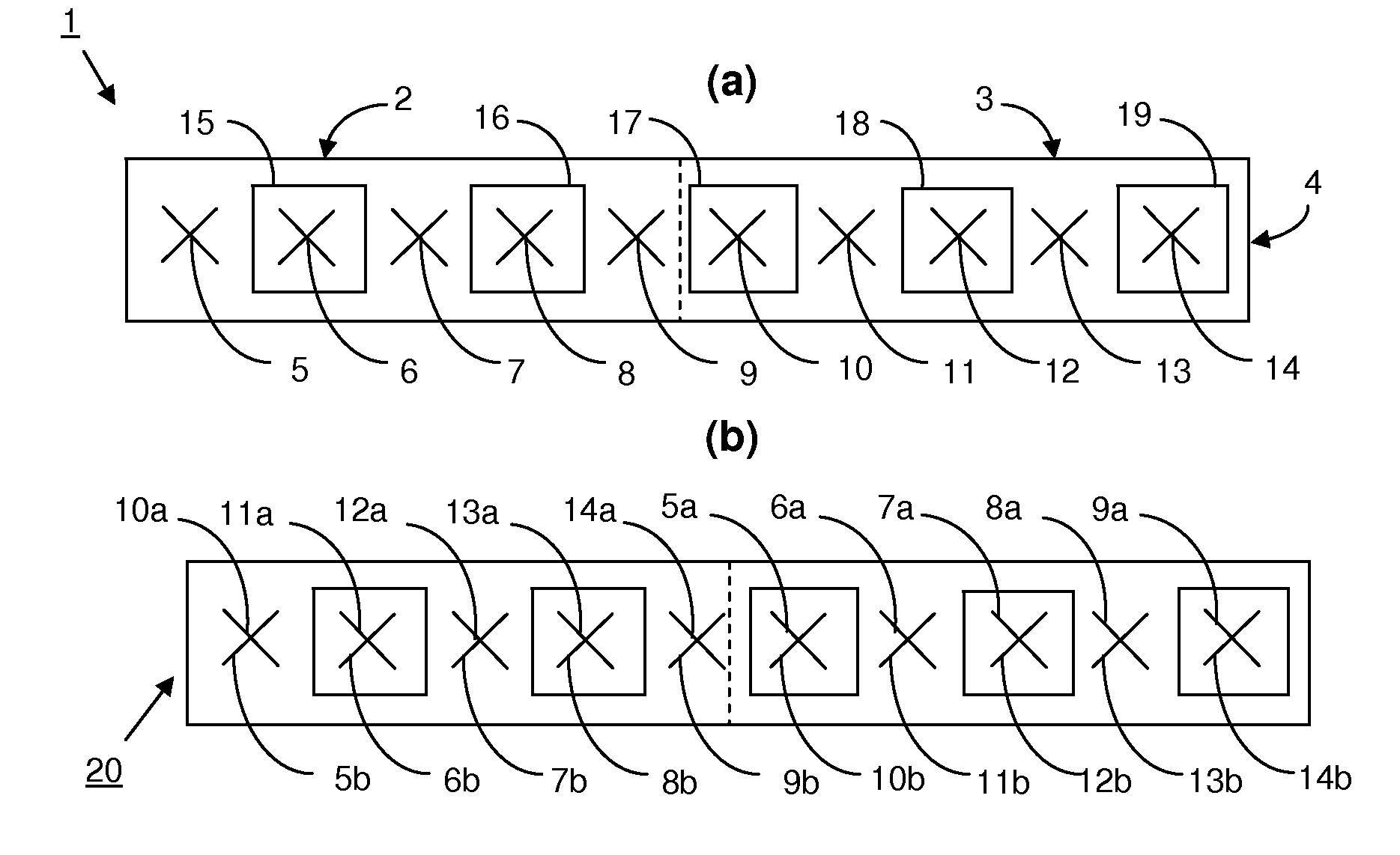
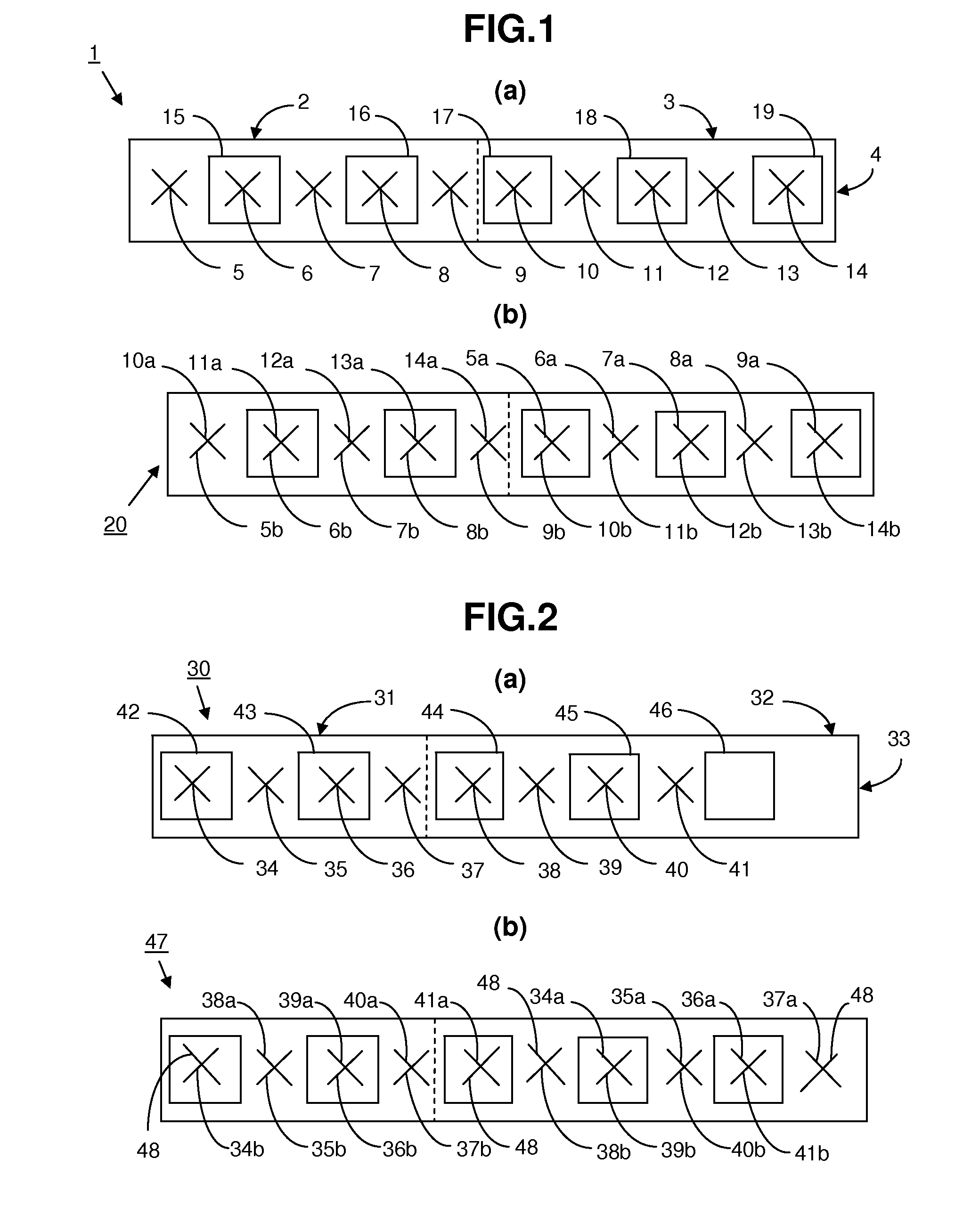
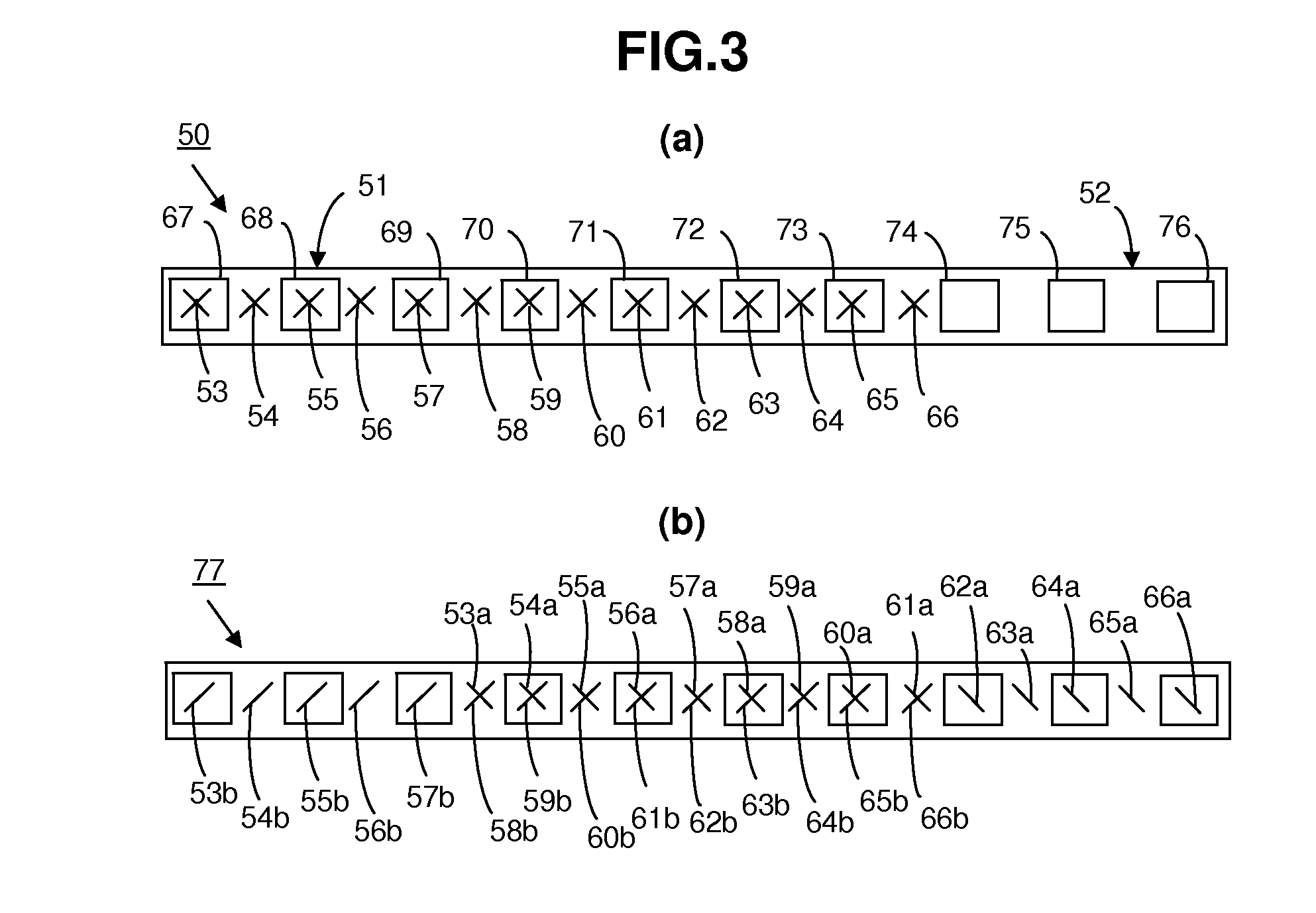
[0027]The radiating elements of a single antenna array are devoted to sending / receiving on a single frequency band. A dual-polarization radiating element is normally formed of two independent dipoles each comprising two colinear conductor arms with a given polarization, positive or negative, for sending / receiving radio signals. What will be described for each polarization, represented here by a dipole, also applies when the polarization is represented by a planar antenna or “patch” antenna. The radiating elements are installed longitudinally aligned above a reflector. Depending on their orientation within space, the dipoles may radiate or receive electromagnetic waves along two polarization channels, for example, a horizontal polarization channel, and a vertical polarization channel, or two polarization channels oriented +45° and −45° relative to the vertical. Each dipole of a radiating element is linked by a feed line to an outside source of power that defines its phase and amplitu...


PUM


Abstract

The object of the present invention is a crosspolar multiband panel antenna comprising, within a single chassis, at least two antenna arrays operating within different frequency bands, each antenna array comprising at least two cross-polarization radiating elements separated by a distance inter-elements, each radiating element comprising a first polarization and a second polarization, the second polarization being orthogonal to the first polarization. The first polarization and the second polarization of each antenna array are physically separated by a distance equal to or greater than the distance inter-elements. The first polarizations and the second polarizations of each antenna array being respectively separated by one another by the distance inter-elements.

Description

CROSS-REFERENCE[0001]This application is based on French Application No. 11,62,388 filed on Dec. 23, 2011, the disclosure of which is hereby incorporated by reference thereto in its entirety, and the priority of which is hereby claimed under 35 U.S.C. §119.BACKGROUND[0002]This invention relates to the field of telecommunication antennas transmitting radio waves in the hyperfrequency range, using radiating elements. It particularly relates to antennas called crosspolar multiband panel antennas. A panel antenna is made up of multiple antenna arrays, such as patch antenna arrays or dipole arrays that work in a given frequency band, which are more particularly in a given frequency band that are more particularly intended for cellular telephony applications.[0003]A telecommunication antenna, for example one installed in a base station of a mobile telephony network, sends and receives radio waves along frequencies specific to the telecommunication system operated by that antenna. To do so...

Claims


Application Information

Patent Timeline
Patent Type & Authority Applications(United States)
IPC IPC(8): H01Q21/26H01Q21/30H01Q5/48
CPCH01Q21/30H01Q21/26H01Q1/24H01Q1/246H01Q5/28H01Q5/48H01Q21/062H01Q21/08H01Q21/24H01Q21/28
Inventor DAUGUET, STEPHANEHAREL, JEAN-PIERRE
Owner ALCATEL LUCENT SAS
Why Eureka
Try Eureka