Prosthetic element

a prosthetic element and element technology, applied in the field of prosthetic elements, can solve the problems of insufficient edge strength of the restoration, increased tool wear during finishing, and insufficient strength of the edge preparation of the restoration, and achieve the effect of limited service li

Active Publication Date: 2014-12-18
STRAUMANN HLDG AG
View PDF20 Cites 24 Cited by
  • Summary
  • Abstract
  • Description
  • Claims
  • Application Information

AI Technical Summary

Benefits of technology

[0086]As mentioned above, the present invention allows for adapting physical subtleties and colour nuances in one single body by a focused phase conversion. Laser irradiation can, however, also be used for providing a gloss to the prosthetic element. Thereby, the outermost surface 20 (See FIG. 5) of the basic body 19A or the glass-ceramic body is melted by means of laser irradiation followed by solidification of the melted material. This further contributes to the aesthetical appearance of the prosthetic element.
[0087]With regard to the CAD / CAM method, laser irradiation can further be used for cutting the basic body or the glass-ceramic body into the desired shape for the final prosthetic element. Thereby, the machining step of a conventional CAD / CAM method and, consequently, the use of expensive diamond-cutting tools that have limited service life due to wear can be avoided. Ultimately, a fully automated and fully controlled production process for ready-to-insert dental prosthesis can be achieved using only laser equipment with regard to the cutting of the material block and the formation of crystalline phase(s) within the material.

Problems solved by technology

Due to the high strength and toughness imparted by the lithium disilicate crystalline phase, however, it has been shown that application of this method results in increased tool wear during finishing and insufficient edge strength of the restorations prepared especially when their thickness falls within a range of only a few hundreds of micrometers.
Although U.S. Pat. No. 7,452,836 allows for achieving materials having a flexural strength which might be sufficient for the restoration of multiple missing teeth in the front (3-unit bridges), its strength is still not sufficient for posterior bridges or large restorations.
Because of its exceptionally high mineral content, enamel is a brittle tissue unable to withstand the forces of mastication without fracture unless it has the support of the more resilient dentin.
However, as a feldspathic ceramic, the material according to WO 2010 / 010082 does not exhibit suitable mechanical properties for indications such as multiple anterior or posterior unit-bridges.
In both the materials according to U.S. Pat. No. 5,939,211 and WO 2010 / 010082, the presence of physically distinct component layers and thus of an interface between different components has as a rule a negative impact on the overall stability of the dental restoration.
Also, the methods according to these publications are relatively laborious.

Method used


Image

  • Prosthetic element
  • Prosthetic element
  • Prosthetic element

Examples


example 1

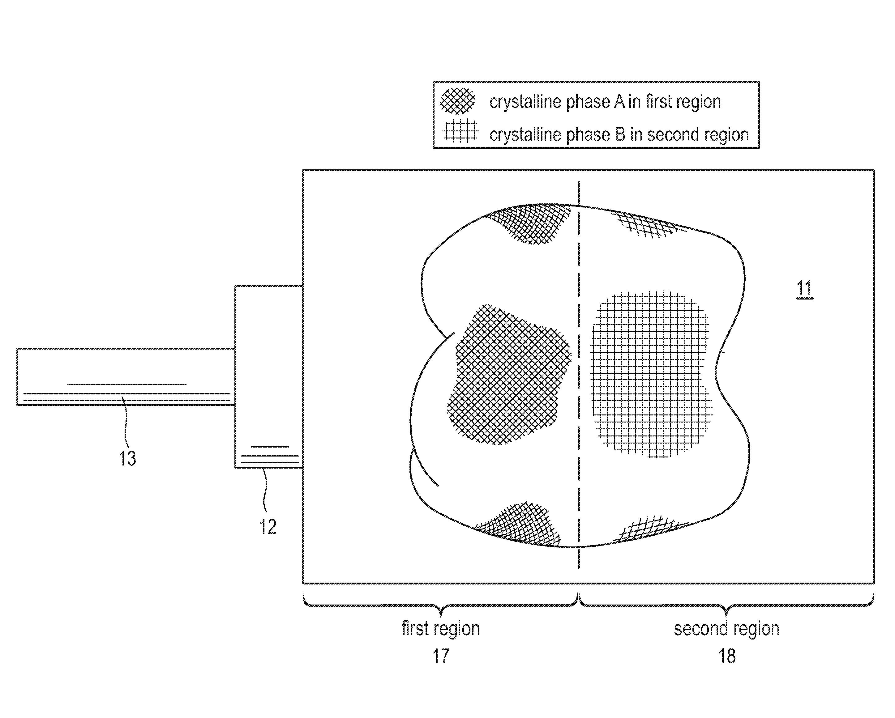
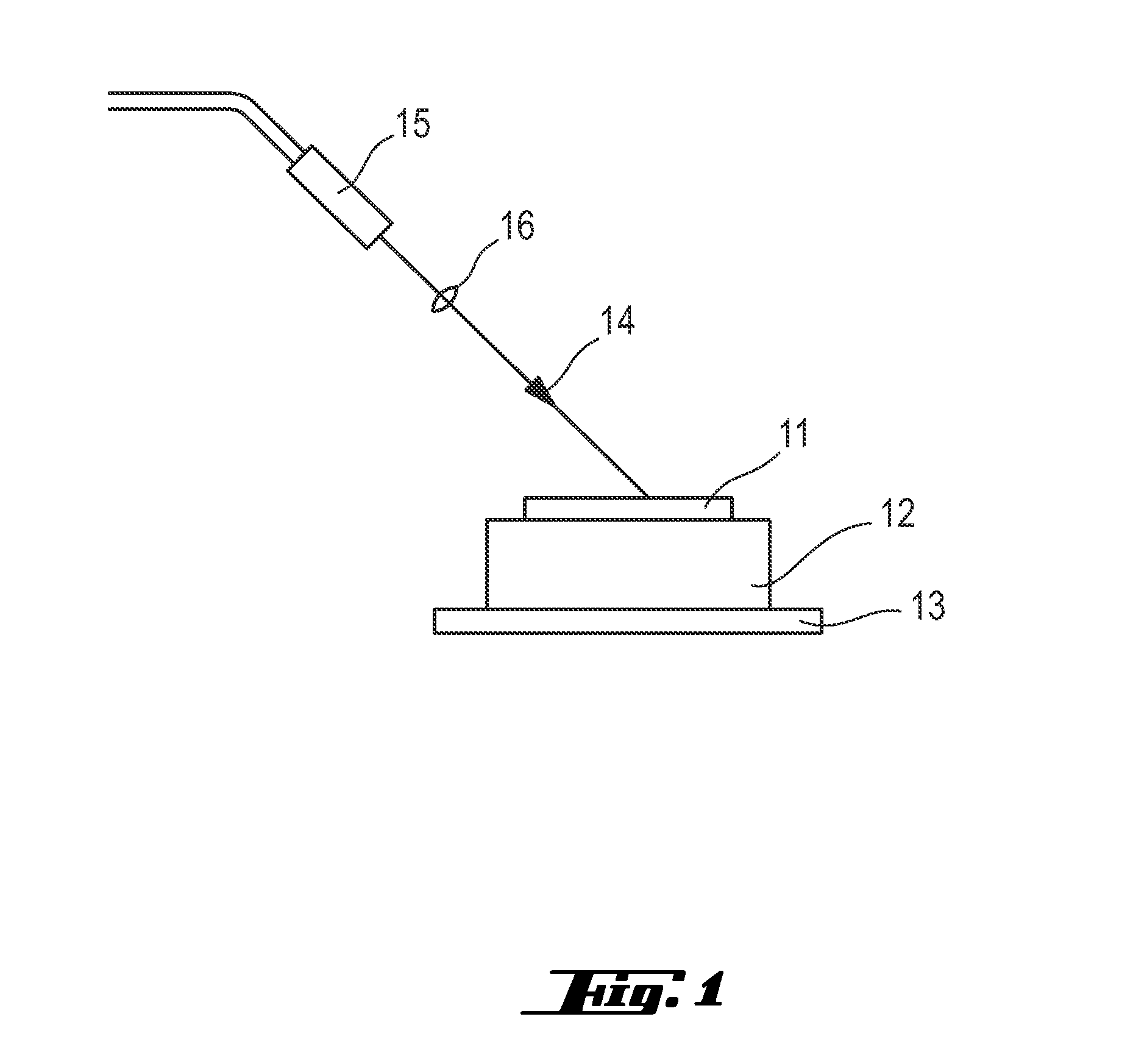
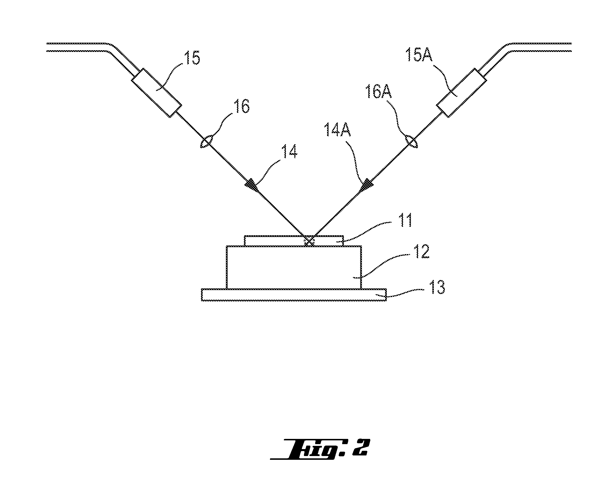
[0097]A bar shaped sample 11 having the above composition is put on a ceramic base plate 12 (table) which itself is arranged on a metal support 13. This arrangement is placed in a chamber where the sample is treated by laser irradiation 14 using a LIMO high power continuous wave (cw) diode laser 15 (wavelength λ=808 nm, optical power=max. 350 W, spot diameter dF=6 mm, uniform beam profile). The laser beam is thereby directed through a focusing lens 16.

[0098]More specific details regarding the laser irradiation in Experiments No.s 1.1 and 1.2 are given in the following:

Experiment No.#1.11.2Sample Positionon tableon tableSample StatenotnotnucleatednucleatedBeam Propagationfocusedfocusedangle 45°angle 45°Beam Diametermm66Optical PowerW180180IntensityW / cm2636.6636.6Irradiation timeMin57

[0099]A comparison of Experiments 1.1 and 1.2 reveals that during the laser irradiation treatment a translucent violet colour starts to spread from the top to the bottom, followed by a white colour propag...

example 2

[0100]Samples having the above composition are preheated in a first step during 1 min at 150 W and 1 min at 120 W before laser irradiation treatment using the laser specified in Example 1. More specific details regarding the laser irradiation in Experiment No. 2 are given in the following:

Experiment No.#2Sampleon tablePositionSample Statenucleated glassBeamfocusedPropagationangle 45°Beam Diametermm6Optical PowerW190IntensityW / cm2672.0IrradiationMin3time

[0101]By this treatment, a glass-ceramic sample comprising crystalline phases of white and yellow colour is obtained. The presence of the crystalline phases generated by laser irradiation is confirmed by XRD (X-ray diffraction) measurements which reveal the presence of 39.8% of beta-spodumene (LiAlSi2O6), 16.3% of lithium disilicate, 0.8% of dilithium phyllo-disilicate, 6.1% of lithiophosphate (Li3PO4), and 0.4% of petalite (LiAlSi4O10).

[0102]Thus, the examples confirm crystallization in the samples by laser irradiation energy using a...


PUM

PropertyMeasurementUnit
wavelengthaaaaaaaaaa

Abstract

A process for preparing a prosthetic element comprising a glass-ceramic body. including the steps of
  • a) providing a basic body comprising an amorphous glass phase and containing the components of the glass-ceramic body to be prepared, and
  • b) transferring energy to the basic body to induce conversion of a starting phase of the material of the basic body into at least one crystalline phase in a confined region. According to the invention, energy is transferred to the confined region of the basic body by laser irradiating said region with a laser beam having a wavelength of at least 500 nm.

Description

FIELD OF THE INVENTION[0001]The present invention relates to a process for preparing a prosthetic element comprising a glass-ceramic body, to a prosthetic element obtainable by this process, as well as to the use of said prosthetic element for a dental restoration.BACKGROUND[0002]Glass-ceramic materials comprise an amorphous (glass) phase and one or more crystalline (ceramic) phases embedded in the amorphous phase. Due to the presence of both an amorphous and a crystalline phase, glass-ceramics share many properties with both glasses and ceramics. They are used in a variety of different technical fields, for example as cooktops, cookware and bakeware, as a substrate for magnetic disks, as high performance reflectors for digital projectors or as prosthetic elements.[0003]Glass-ceramics are of particular interest in the field of restorative dentistry, since there is a high demand for prosthetic elements which exhibit excellent characteristics comparable to those of natural teeth in te...

Claims


Application Information

Patent Timeline
Patent Type & Authority Applications(United States)
IPC IPC(8): A61C13/00A61K6/027A61C13/083
CPCA61C13/0018A61C13/083A61C13/0022A61C13/0004A61K6/0273C03C10/0027C03C23/0025A61C13/00A61K6/833C03B32/02
Inventor KOUNGA, ALAINAPPERT, CHRISTOPHDZIADOWIEC, IWONA
Owner STRAUMANN HLDG AG
Why Eureka
Try Eureka