
Patient mounted MRI and ct compatible robot for needle guidance in interventional procedures

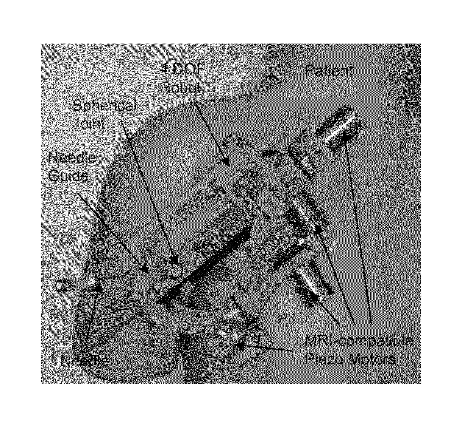
a technology of ct and robot, which is applied in the field of patient mountable robot, can solve the problems of increased cost, prolonged sedation time, and difficult access of patients in the mri, and achieve the effects of improving clinical workflow, better targeting, and improving access

Active Publication Date: 2014-12-18
CHILDRENS NAT MEDICAL CENT
View PDF4 Cites 25 Cited by
  • Summary
  • Abstract
  • Description
  • Claims
  • Application Information

AI Technical Summary

Benefits of technology

This patent introduces a new robotic system that can be used in MRI and CT scanners for better targeting and improved clinical workflow. The system allows for better access with cylindrical bore MRI scanners and is designed to minimize patient movement during needle placement procedures. The device is compact and can be easily sterilized, making it a cost-effective solution. This invention is useful for interventional radiology procedures and can be used in adults and children for biopsy, drainage, and ablations. Overall, this technology improves the accuracy and efficiency of needle based procedures.

Problems solved by technology

The inability to leverage the imaging capabilities of the MRI itself and the manual nature of needle placement lead to increased cost, anxiety, and in some cases prolonged sedation time, especially for the youngest and most anxious patients.
Moreover, while the MRI could also be used for guiding the needle placement, patient access in the MRI can be difficult, especially for closed bored scanners.
The conventional two-step workflow can result in anxiety for the patient, prolonged sedation time when sedation is needed for younger patients, radiation exposure from the fluoroscopic imaging, and may increase cost due to the use of both the fluoroscopy and MRI suite.
In MRI guided interventions, patient access can be difficult, especially for closed bored scanners.
The high-strength magnetic field currently present in a clinical MRI environment makes developing MRI-compatible equipment a challenge.
However, none of the conventional patient-mounted robots for percutaneous interventions address the above-noted shortcomings.
Such a mechanical design results in a minimal height profile which is an important issue considering the small diameter of the MRI scanner's bore (typically 60 cm).

Method used


Image

  • Patient mounted MRI and ct compatible robot for needle guidance in interventional procedures
  • Patient mounted MRI and ct compatible robot for needle guidance in interventional procedures
  • Patient mounted MRI and ct compatible robot for needle guidance in interventional procedures

Examples


Embodiment Construction

[0060]Referring to the drawings, like reference numerals designate identical or corresponding parts throughout the several views.

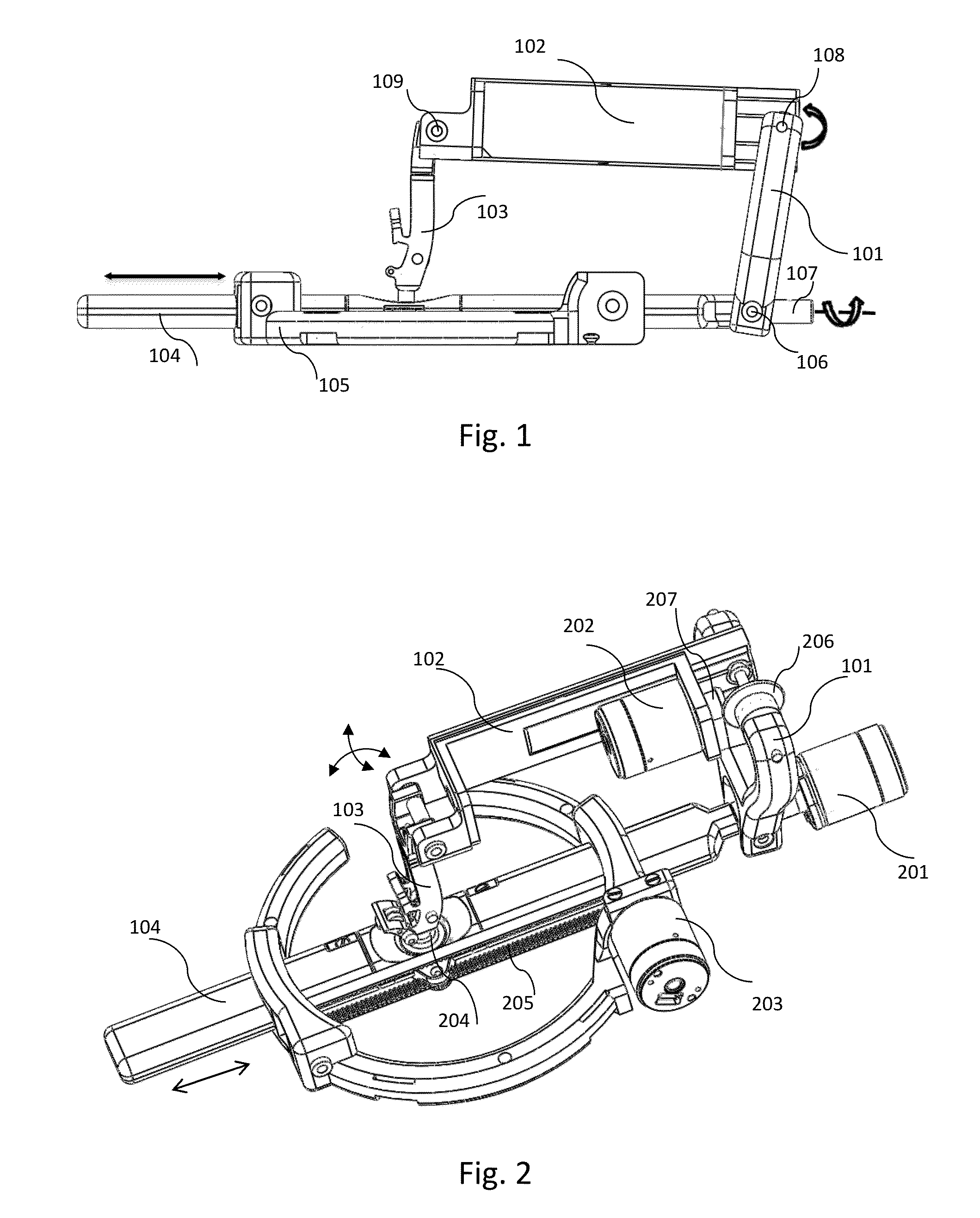
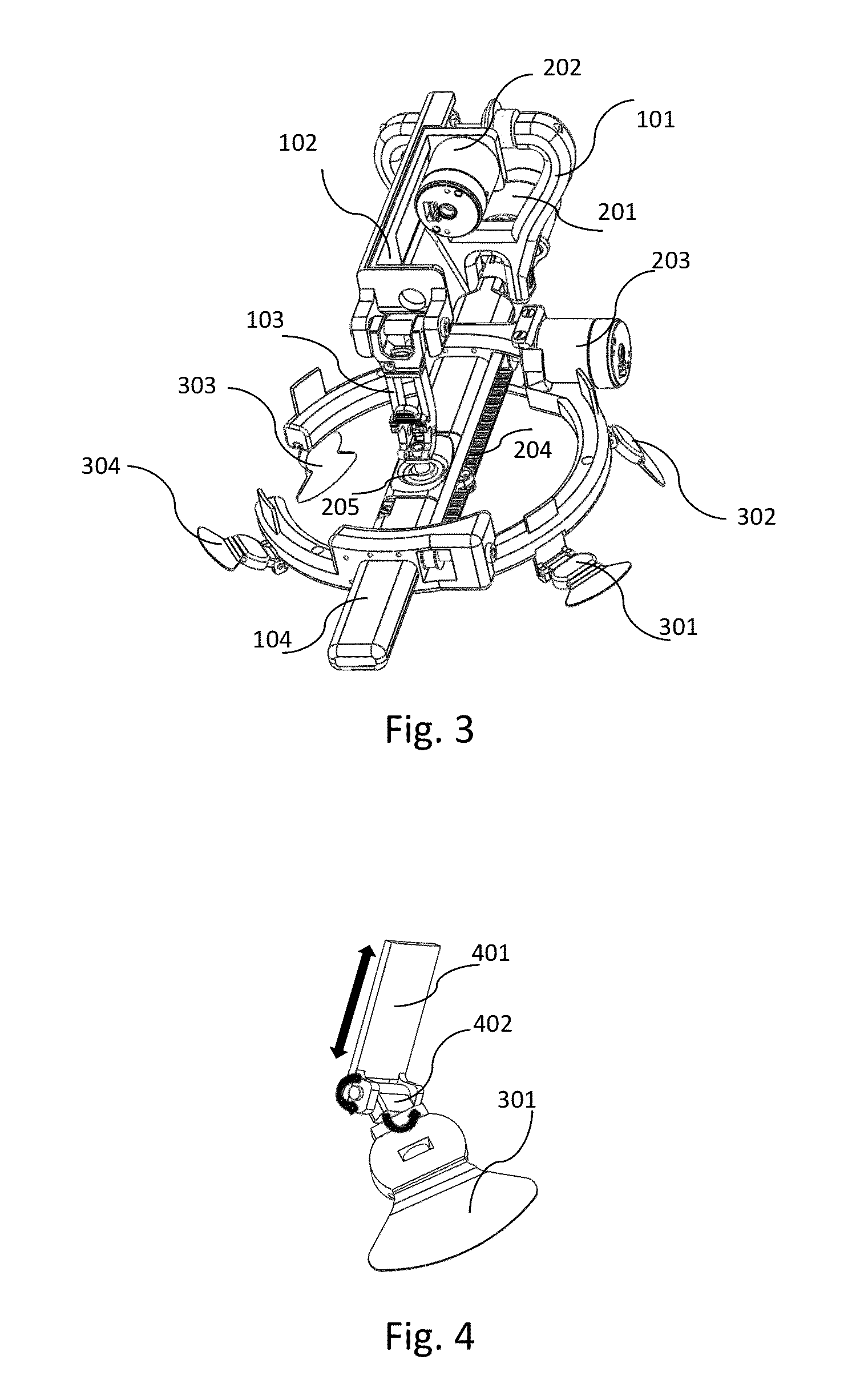
[0061]One non-limiting illustrative embodiment of the invention is shown in FIGS. 1 to 6. FIG. 1 shows an overview of a 4-link parallel mechanism with a sliding base. This mechanism has three degrees of freedom (DOF), i.e., two DOFs for adjusting an orientation of a needle and one for translational motion. This parallel mechanism consists of four links 101, 102, 103, and 104. The base link 104 can slide back and forth which adds translational motion to the mechanism. Part 105 is the part that is fixed to a patient's body using adjustable mechanism which will be explained in more detail later. Part 105 has sliding holes in which the link 104 slides through these holes back and forth. The link 101 pivots with respect to the link 104 in two directions through shafts 106 and 107. The link 102 pivots with respect to the link 101 through shaft 108. The link 103 ...


PUM


Abstract

A patient mountable robot includes a four link mechanism, three actuators, and a first robot base. The mechanism includes four links that form a closed loop structure. The four links include a base link that includes a spherical joint. The mechanism provides two rotational degrees of freedom about the spherical joint for a needle that is configured to pass through the spherical joint. A first actuator is attached to the mechanism and moves the mechanism to provide the first of the two rotational degrees of freedom. A second actuator is attached to the mechanism and moves the mechanism to provide the second of the two rotational degrees of freedom. The base link of the mechanism passes through the first robot base. A third actuator is attached to the first robot base and linearly translates the base link so that a translational degree of freedom is provided for the needle.

Description

CROSS REFERENCE TO RELATED APPLICATION[0001]This application is based upon and claims the benefit of priority from U.S. Provisional Patent Application No. 61 / 835,654, filed on Jun. 17, 2013, the entire contents of which are incorporated herein by reference.BACKGROUND[0002]I. Field of the Disclosure[0003]The present invention relates to a patient mountable robot that will help a physician to reach a point of interest in a patient's body, and in particular, during an MRI or CT guided intervention in which the patient is inside a bore of a scanner. In such a configuration it is difficult to reach, for example, the patient's joints for arthrography or other similar procedure. Thus, the patient mountable robot is intended to reduce trial and error, increase precision for a needle placement, and be low cost compared to conventional large and bulky robots.[0004]II. Description of the Related Art[0005]The “background” description provided herein is for the purpose of generally presenting th...

Claims


Application Information

Patent Timeline
Patent Type & Authority Applications(United States)
IPC IPC(8): A61B19/00A61M5/00
CPCA61B19/2203Y10S901/01A61M5/007A61B2017/3407A61M5/427A61M5/46A61B2090/3762A61B2090/374A61B34/30
Inventor CLEARY, KEVINMONFAREDI, REZASZE, RAYMONDSHARMA, KARUNSAFDAR, NABILESEIFABADI, REZA
Owner CHILDRENS NAT MEDICAL CENT
Learn More