Stencil mapped shadowing system

Active Publication Date: 2014-12-25
SNAP INC
View PDF4 Cites 30 Cited by
  • Summary
  • Abstract
  • Description
  • Claims
  • Application Information

AI Technical Summary

Benefits of technology

[0011]
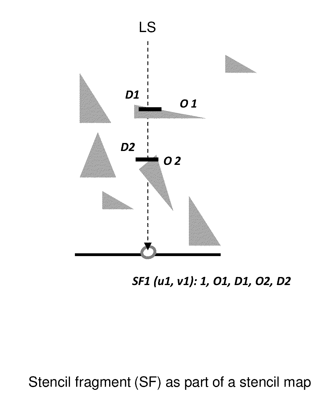
Prior art shadowing, being based on huge acceleration structures, suffers of high construction cost and traversal costs of such structures, and millions of expensive intersection tests. Our shadowing, based on stencils, eliminates the use of acceleration structures and cuts off the majority of intersection tests. The scene is structured of a uniform grid of cells. The relevant part of scene data, critical for shadowing of all visible intersection points in a cell, is registered in the local stencil map, as a volumetric data. Due to these stencils, a

Problems solved by technology

Ray tracing is a high computationally expensive algorithm.
For this reason, there has been a lot of effort put into finding the best parallel decomposition for ray tracing.
However, if a very large models need to be rendered, the scene data have to be distributed over the memories, because the local memory of each processor is not large enough to hold the entire scene.
Then demand driven approach suffers from massive copies and multiplications of geometric data.
However, rendering cost per ray and the number of rays passing through each subset of database are likely to vary (e.g. hot spots are caused by viewpoints and light sources), leading to severe load imbalances, a problem which is difficult to solve either with static or dynamic load balancing schemes.
Efficiency thus tends to be low in such systems.
However, since the number of objects may vary dramatically from voxel to voxel, the cost of tracing a ray through each of these voxels will vary and therefore this approach may lead to severe load imbalances.
Generating data distributions which adhere to all three criteria is a difficult problem, which remains unsolved in prior art.
Most data distributions are limited to equalizing the memory overhead for each processor.
Another problem in ray tracing is the high processing cost of acceleration structures.
The cost of testing each ray against each polygon is prohibitive, so such systems typically use accelerating structures (such as Octree, KD-tree, other binary trees, bounding boxes, etc.) to reduce the number of ray/polygon intersection tests that must be perfor

Method used


Image

  • Stencil mapped shadowing system
  • Stencil mapped shadowing system
  • Stencil mapped shadowing system

Examples


implementation embodiments

[0078]Our algorithm based on stencil can be efficiently implemented on a single processor systems, as well as on multiprocessor systems, general purpose processors, special purpose processors, multicore processors, and GPUs. These processors can be integrated in different computing systems such as single processor computing systems, parallel computers, PC-level computers, information server computers, cloud server computers, laptops, portable processing systems, tablets, Smartphones, and other computer-based machines. Although a sequential computing system is capable of performing our shadowing algorithm, however, parallel computing system would do it for larger models. Today, a typical classification by model size is to small models of up to few hundreds of polygons, medium models of up to a few millions of polygons, and large models of up to billions of polygons. Due to our enhanced load balancing, the performance scalability is linear to the number of participating processors. Th...


PUM


Abstract

Aspects comprise shadowing system as part of ray tracing. It is based on uniform grid of cells, and on local stencils in cells. The acceleration structures are abandoned along with high traversal and construction costs of these structures. The amount of intersection tests is cut down. The stencils are generated in the preprocessing stage and utilized in runtime. The relevant part of scene data, critical for shadowing of all visible intersection points in a cell, is registered in the local stencil map, as a volumetric data. The runtime use of stencils allows a complete locality at each cell, enhanced utilization of processing resources and load balancing of parallel processing.

Description

CROSS-REFERENCE TO RELATED CASES[0001]The present application claims priority based on U.S. Provisional Application No. 61 / 894,144 filed Oct. 22, 2013 entitled “Ray Shadowing Method Utilizing Geometrical Stencils”; and is a Continuation-In-Part of the U.S. application Ser. No. 13 / 726,763 filed Dec. 26, 2012 entitled “Method and Apparatus for Interprocessor Communication Employing Modular Space Division”; all of which are hereby incorporated by reference.FIELD OF THE INVENTION[0002]The present invention relates generally to solving data-parallel processing and, more particularly, to data-parallel ray tracing technology enabling real time applications and highly photo-realistic images.BACKGROUND OF THE INVENTION[0003]Ray-tracing is a technique for generating images by simulating the behavior of light within a three-dimensional scene by typically tracing light rays from the camera into the scene, as depicted in FIG. 1A. In general two types of rays are used. The ray that comes from the...

Claims


Application Information

Patent Timeline
IPC IPC(8): G06T15/06G06T15/60G06T15/08
CPCG06T15/06G06T15/08G06T2215/12G06T2200/04G06T15/60G06F9/5061G06F2209/502G06T2210/52
Inventor BAKALASH, REUVEN
Owner SNAP INC
Why Eureka
Try Eureka