

Polar Modulation
a modulator and phase amplitude technology, applied in the field of modulators, can solve the problems of less well suited to use in the wider band radio system, the bandwidth of phase and amplitude modulation signals used for modulating the transmitter, and the bandwidth of composite signals, etc., to achieve fast operation, low complexity, and high bandwidth reduction
Active Publication Date: 2014-12-25
TELEFON AB LM ERICSSON (PUBL)
View PDF4 Cites 3 Cited by
- Summary
- Abstract
- Description
- Claims
- Application Information
AI Technical Summary
Benefits of technology
The patent describes a method for generating a composite, amplitude and phase, modulated carrier signal. By using a modulator that modulates the frequency of the carrier signal through a differentiated signal, the method provides a way to achieve both amplitude and phase modulation using a single device. The method can also adapt to high-bandwidth events and reduce the bandwidth of the composite signal, improving transmission quality and reducing noise. The technical effect of this patent is to provide a more efficient and effective way to generate high-quality carrier signals.
Problems solved by technology
However, they are less well suited to use in wider band radio systems such as the Third Generation Partnership Project Long Term Evolution, referred to, for brevity, as LTE.
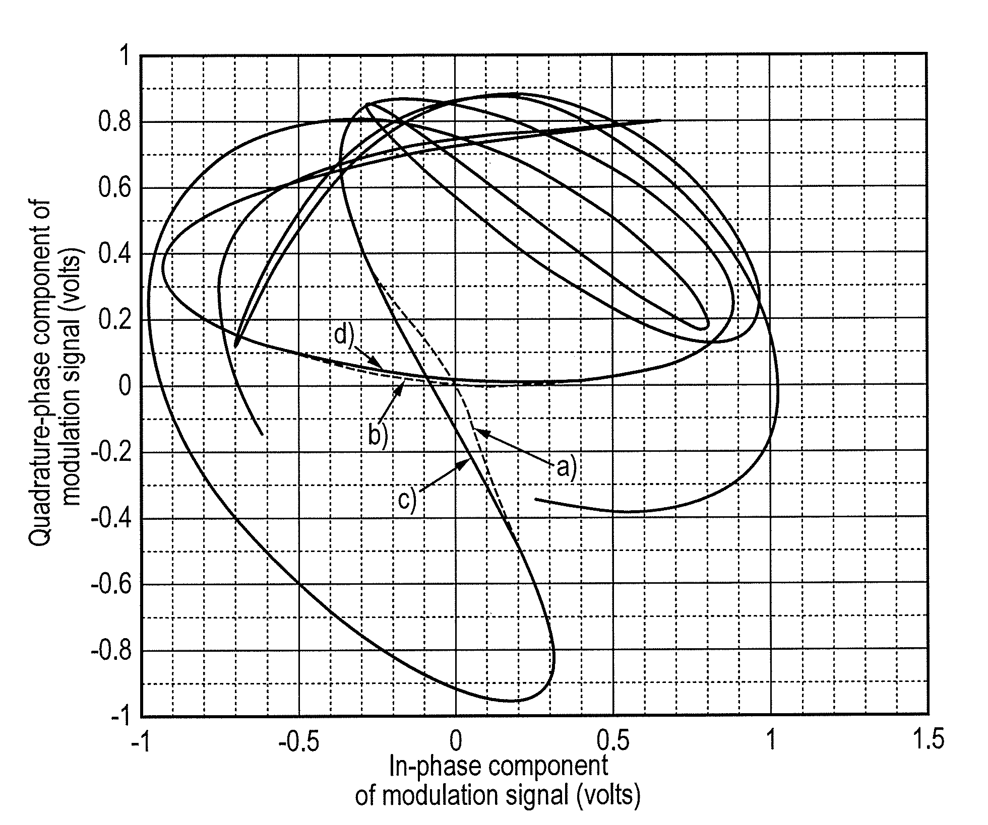
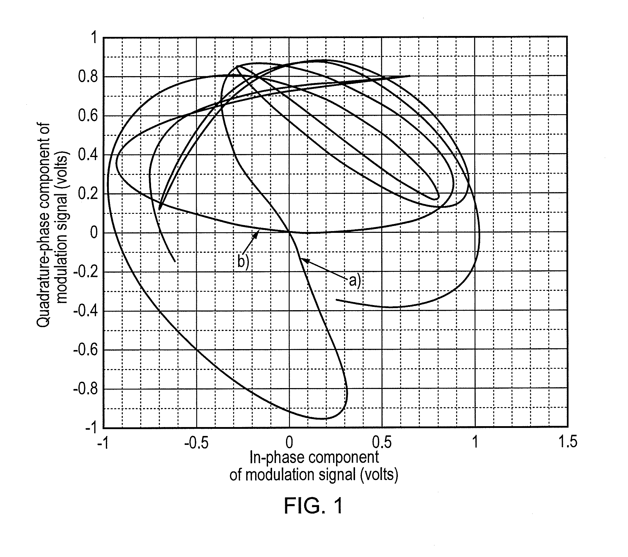
A problem with polar transmitters is that the bandwidth of the phase and amplitude modulation signals used for modulating the transmitter is much wider than the bandwidths of in-phase and quadrature-phase (I / Q) components of a modulation signal.
An additional problem with a polar transmitter is that the bandwidth of the composite signal, that is, a carrier signal after modulation by both the amplitude and phase modulation signals, is wider than the bandwidth of both the amplitude and phase modulation signals.
This is especially a problem with systems such as LTE, which have a high modulation bandwidth.
A low ratio of duplex distance to modulation bandwidth can present a challenge.
Therefore, in LTE the worst ratio of duplex distance to modulation bandwidth is 2.6 times smaller than in WCDMA, making it very challenging to build a polar modulator.
Another challenge when building a polar modulator for LTE is the very high frequency deviation required in a 2-point phase locked loop (PLL).
It is very challenging to generate such a wide linear tuning range and also a wide deviation reduces the available tuning range, limiting the ability to support multiple bands in one digitally controlled oscillator (DCO).
Yet another challenge with polar modulation is the time alignment requirement.
Method used
View moreImage
Smart ImageViewing Examples

Examples
first embodiment
[0049]FIG. 6 is a block schematic diagram of a signal processing stage;
[0050]FIG. 7 is a flow chart of signal processing;
[0051]FIG. 8 is a block schematic diagram of a first embodiment of an amplitude modulation stage;
second embodiment
[0052]FIG. 9 is a block schematic diagram of an amplitude modulation stage;
[0053]FIG. 10 is a block schematic diagram of a phase modulation stage;
[0054]FIG. 11 is a block schematic diagram of a second embodiment of a signal processing stage;
[0055]FIG. 12 is a flow chart of a method of modulation; and
[0056]FIG. 13 is a graph showing spectra before and after modification of the modulation signal;
Login to View More PUM
 Abstract
A modulator (100) comprises a polar generation stage (120) arranged for generating an amplitude component and a phase component of a modulation signal, a differentiator stage (150) arranged for generating a differentiated phase component by differentiating the phase component; and an event detection stage (170) arranged for detecting a high bandwidth event by detecting at least one of the amplitude component and the differentiated phase component meeting an event criterion. An inversion stage (130) is arranged for generating a modified amplitude component by inverting the amplitude component in response to detecting the high bandwidth event. A phase offset stage (150) is arranged for generating a modified differentiated phase component by, in response to detecting the high bandwidth event, adding to the differentiated phase component a phase offset having a magnitude of 180 degrees and a sign opposite to a sign of the differentiated phase component. An amplitude modulation stage (300) is arranged for employing the modified amplitude component to modulate the amplitude of a carrier signal, and a phase modulation stage (200) is arranged for employing the modified differentiated phase component to modulate the frequency of the carrier signal.
Description
FIELD OF THE DISCLOSURE[0001]The present disclosure relates to a modulator, a transmitter comprising the modulator, and a method of modulation.BACKGROUND TO THE DISCLOSURE[0002]The polar modulator is a good architecture for a radio transmitter when moving to more digitally intensive implementations. A transmitter for the Global System for Mobile Communications (GSM) and for Enhanced Data rates for GSM Evolution (EDGE), and comprising a polar modulator, is disclosed in “Spur-free all-digital PLL in 65 nm for Mobile Phones”, B. Staszewski et al, IEEE International Solid State Circuits Conference, session 3.1, 2011. A transmitter for Wideband Code Division Multiple Access (WCDMA), and comprising a polar modulator, is disclosed in “A fully digital multimode polar transmitter employing 17b RF DAC in 3G mode”, Z. Boos et al, IEEE International Solid State Circuits Conference, session 21.7, 2011. Such polar transmitters can be very power efficient. However, they are less well suited to use...
Claims
Login to View More Application Information
Patent Timeline
 IPC IPC(8): H04L27/34H04L27/36
CPCH04L27/363H04L27/3405H04L27/361
InventorNILSSON, MAGNUSVAANANEN, PAAVOVILHONEN, SAMI TAPANI
OwnerTELEFON AB LM ERICSSON (PUBL)