Time-based digitizer for pet photodetector

a time-based, digital camera technology, applied in the field of imaging, can solve the problem that the cost of a scanner is directly related to the number of detection elements

Active Publication Date: 2015-01-01
THE BOARD OF TRUSTEES OF THE LELAND STANFORD JUNIOR UNIV
View PDF7 Cites 11 Cited by
  • Summary
  • Abstract
  • Description
  • Claims
  • Application Information

AI Technical Summary

Problems solved by technology

The cost of a scanner is directly related to the number of detection elements in the system.

Method used


Image

  • Time-based digitizer for pet photodetector
  • Time-based digitizer for pet photodetector
  • Time-based digitizer for pet photodetector

Examples


Embodiment Construction

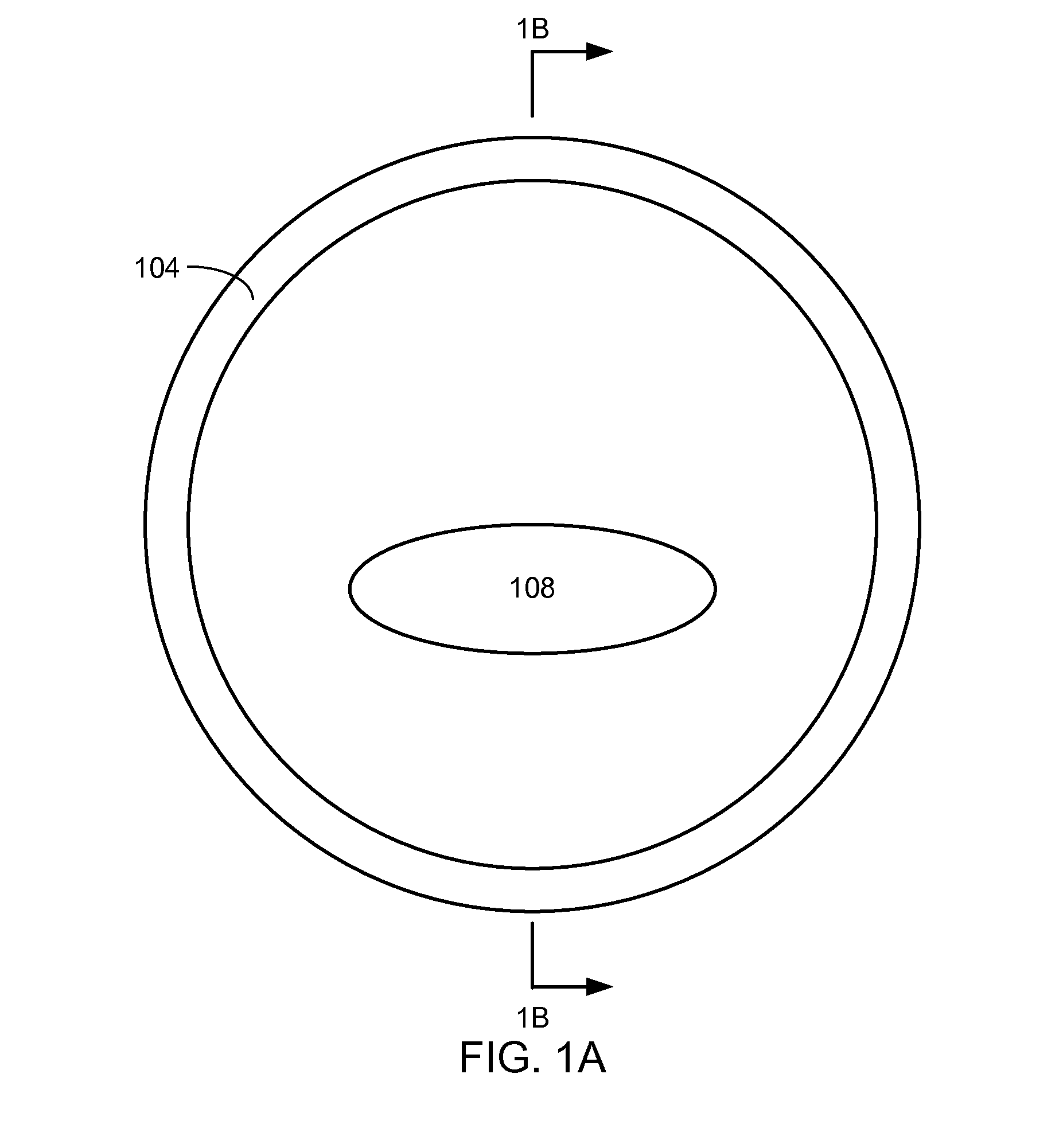
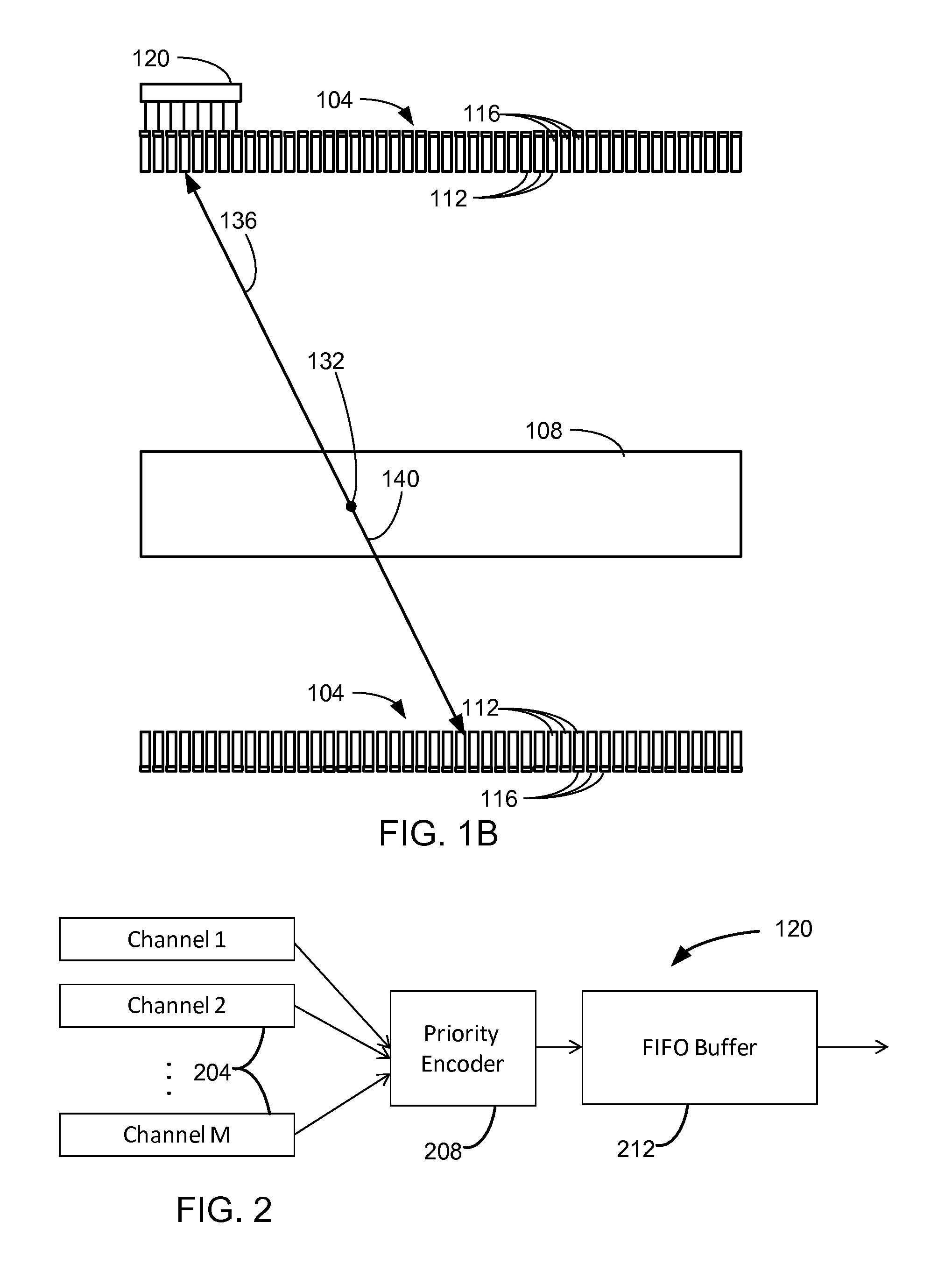
[0018]FIG. 1A is a cross sectional view of a PET scanner 104 with an object 108 that is used in an embodiment of the invention. FIG. 1B is a cross sectional view of the PET scanner 104 along cut line 1B that shows that the PET scanner 104 is made of a plurality of individual scintillation crystals 112. Each scintillation crystal 112 optically coupled to at least one photodetector 116, so that that photodetector 116 receives photons from the scintillation crystal 112. The photodetector 116 may be, for example, a position sensitive avalanche photodiode (PSAPD), a silicon photomultipliers (SiPM), or a photomultiplier tube. Preferably, the photodetector 116 is a SiPM. Each photodetector 116 is connected to a readout device 120. Only one of the readout devices is shown. In this example, the readout device 120 that is shown is connected to eight photodetectors 116.

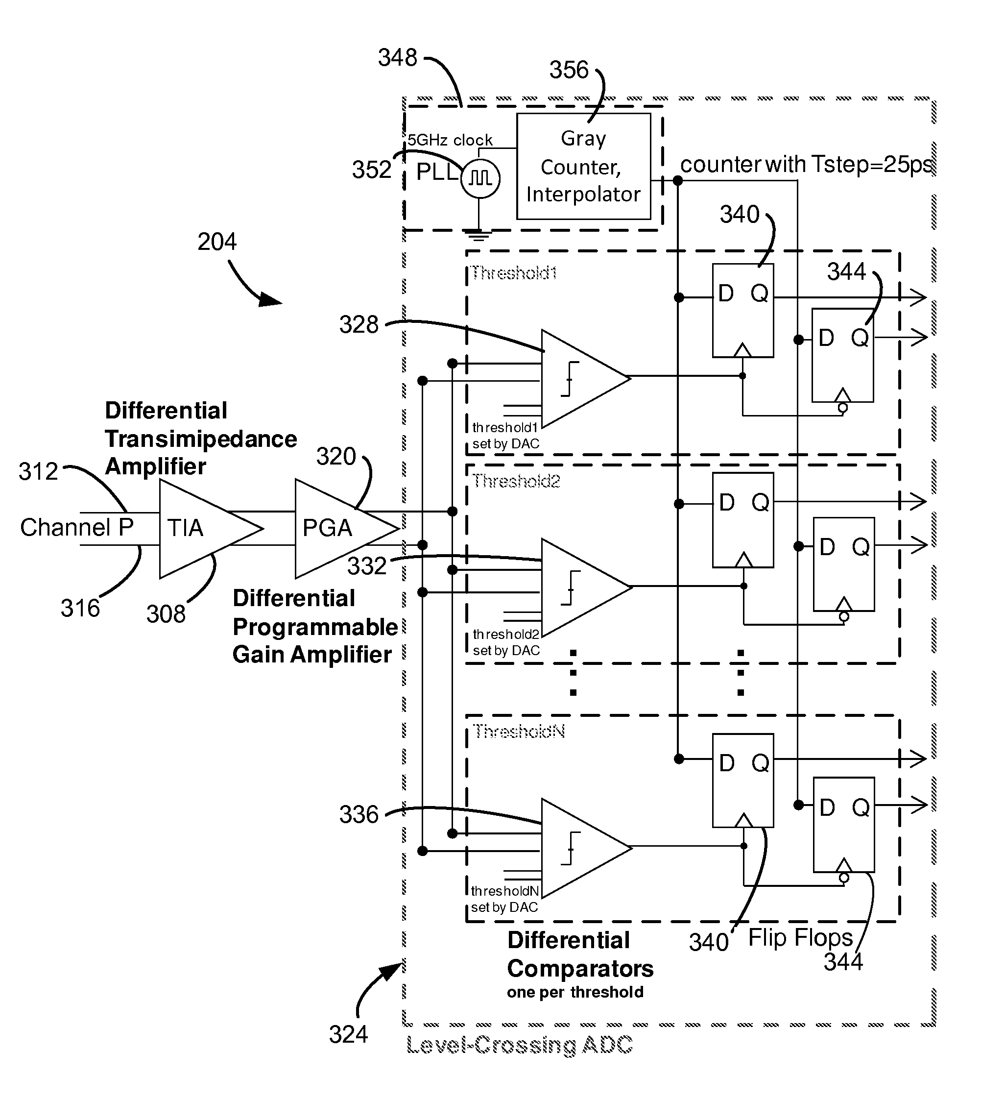
[0019]FIG. 2 is a circuit block diagram of the readout device 120. The readout device 120 is able to handle M channels, with e...


PUM


Abstract

An integrated circuit in a PET imaging system with a plurality of photo detectors is provided. A plurality of differential transimpedance amplifiers with differential inputs and differential outputs is provided, wherein differential inputs for each differential transimpedance amplifier of the plurality of differential transimpedance amplifiers are electrically connected to a photodetector. A plurality of level crossing analog-to-digital converters is provided wherein differential inputs for each level crossing analog-to-digital converter of the plurality of level crossing analog-to-digital converters are electrically connected to differential outputs of a differential transimpedance amplifier, wherein each level crossing analog-to-digital converter of the plurality of level crossing analog-to-digital converters, comprises a plurality of differential comparators with differential inputs and differential threshold inputs, wherein the differential inputs are electrically connected to the output of the differential outputs of the differential transimpedance amplifier electrically connected to the level crossing analog-to-digital converter and a clock.

Description

CROSS REFERENCE TO RELATED APPLICATIONS[0001]This application claims priority under 35 U.S.C. §119 from U.S. Provisional Patent Application No. 61 / 567,322, filed Dec. 6, 2011, entitled ADJUSTABLE AMPLIFIER AND TIME-BASED DIGITIZER WITH FAST TIMING FOR SIPM- AND ADP-BASED PET PHOTODETECTORS, which is incorporated herein by reference for all purposes.FIELD OF THE INVENTION[0002]A field of the invention is imaging. Example applications of the invention include, but are not limited to imaging using a photodetector. A more specific application of the invention provides a readout for photodetectors in a positron emission tomography system.BACKGROUND OF THE INVENTION[0003]Positron emission tomography (PET) is a diagnostic imaging modality that is used to non-invasively measure the bio-distribution of a radioactive tracer. In positron emission tomography, a positron emitting bare radioactive isotope or an isotope that has been attached to a chemical molecule, is injected into a patient or a...

Claims


Application Information

Patent Timeline
Patent Type & Authority Applications(United States)
IPC IPC(8): G01T1/202G01T1/20G01T1/208G01T1/29
CPCG01T1/208G01T1/2985G01T1/2006G01T1/202A61B6/037A61B6/4208G01T1/1647H03M1/1019H03F3/08H03M1/204E02D29/1427
Inventor LAU, FRANCES W. Y.LEVIN, CRAIG STEVENHOROWITZ, MARK A.CHOI, HWANG HOKIM, JAEHA
Owner THE BOARD OF TRUSTEES OF THE LELAND STANFORD JUNIOR UNIV
Why Eureka
Try Eureka