Solid oxide fuel cell and manufacturing method and manufacturing apparatus for same

a technology of solid oxide fuel cell and manufacturing method, which is applied in the direction of cell components, final product manufacturing, sustainable manufacturing/processing, etc., can solve the problems of increasing the cost of manufacturing process, increasing the risk of cracking in the ceramic adhesive layer at the cell joint portion, and increasing the number of manufacturing processes. , to achieve the effect of reducing the time required for manufacturing, reducing the risk of cracking in the ceramic adhesive layer at the cell joint portion, and small volum

Inactive Publication Date: 2015-01-01
TOTO LTD
View PDF2 Cites 5 Cited by
  • Summary
  • Abstract
  • Description
  • Claims
  • Application Information

AI Technical Summary

Benefits of technology

[0038]In the invention, the adhesive application step and workable hardening step are preferably repeated multiple times. Therefore multiple iterations of the workable hardening step are carried out on the ceramic adhesive applied in the initial adhesive application step. Moisture or solvent within the hardened ceramic adhesive is thus gradually vaporized, and the ceramic adhesive approaches a state capable of withstanding the temperature rise in the startup procedure. After multiple iterations of the adhesive application step and the workable hardening step, multiple joint portions hardened in each of the workable hardening steps are dried by the solvent elimination and hardening step. Hardened moisture or solvent remaining inside ceramic adhesive is extremely small in volume due to the solvent elimination and hardening step, and the hardened ceramic adhesive is in a state able to withstand the temperature rise in the startup procedure. In the present invention, multiple joint portions hardened by multiple workable hardening steps are simultaneously dried until able to withstand the temperature rise of the startup procedure, therefore constituent members can be joined in an airtight manner while reducing the time required for manufacturing.
[0039]Moreover, in the invention thus constituted a workable hardening step is implemented on joint portions other than the cell joint portions after the workable hardening steps on cell joint portions, for which it is extremely important to secure airtightness. As a result, at least 2 workable hardening steps are applied to cell joint portions, and the risk of cracking in the ceramic adhesive layer at the cell joint portions can be enormously reduced without extending required assembly time.

Problems solved by technology

However, when securing airtightness by injecting glass in paste form into joint portions after mechanically affixing constituent members with bolts or the like, the problem arises that two steps are required for a single location, raising costs as the number of manufacturing processes increases.
In addition, when constituent members are affixed using bolts inside a fuel cell module, chrome components vaporize from the bolts when exposed to high temperatures, causing chrome poisoning of the fuel cells leading to degradation of the cells.
The problem can also arise that when sealing is done using glass in order to achieve airtightness at joining portions, boron vaporizes from the glass and causes degradation of the fuel cells by adhering thereto.
The problem for conventional joints using ceramic adhesive, however, has been that a reliable seal could not be made between constituent members at the same time that constituent members are affixed to one another.
That is, because solvent such as water vaporize when a ceramic adhesive is dried after being applied, their volume shrinks, and unless this shrinkage is skillfully controlled, peeling and excessive cracking associated with shrinkage occurs in the ceramic adhesive layer after hardening.
When such peeling or cracking does occur in the ceramic adhesive layer, sufficient sealing properties cannot be secured in those joint portions even though sufficient adhesion strength may be obtained between constituent members.
However, when a ceramic adhesive layer is coated with glass, the number of manufacturing processes increases and the problem of boron evaporation from the glass occurs, so there is no advantage to using the ceramic adhesive.

Method used


Image

  • Solid oxide fuel cell and manufacturing method and manufacturing apparatus for same
  • Solid oxide fuel cell and manufacturing method and manufacturing apparatus for same
  • Solid oxide fuel cell and manufacturing method and manufacturing apparatus for same

Examples


Embodiment Construction

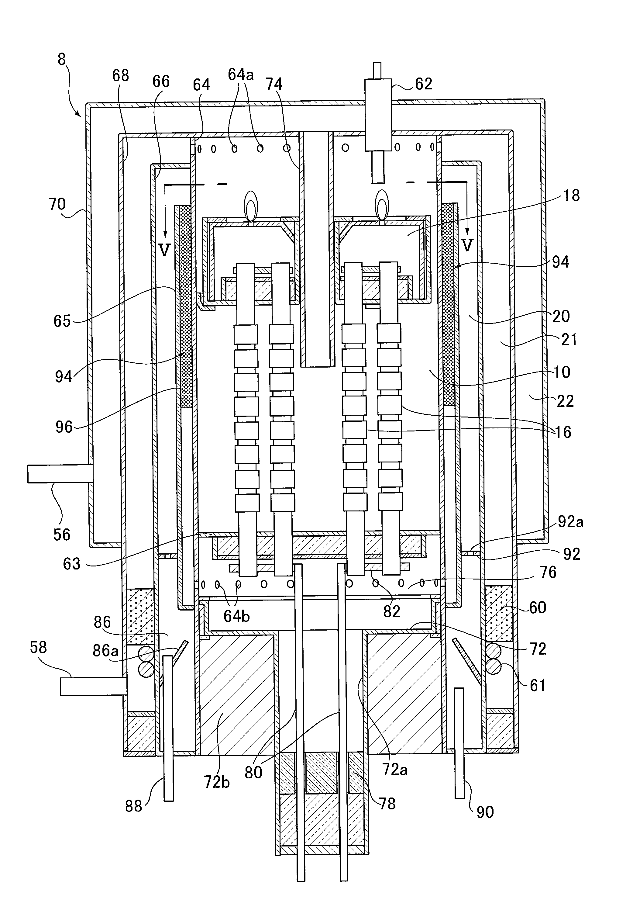
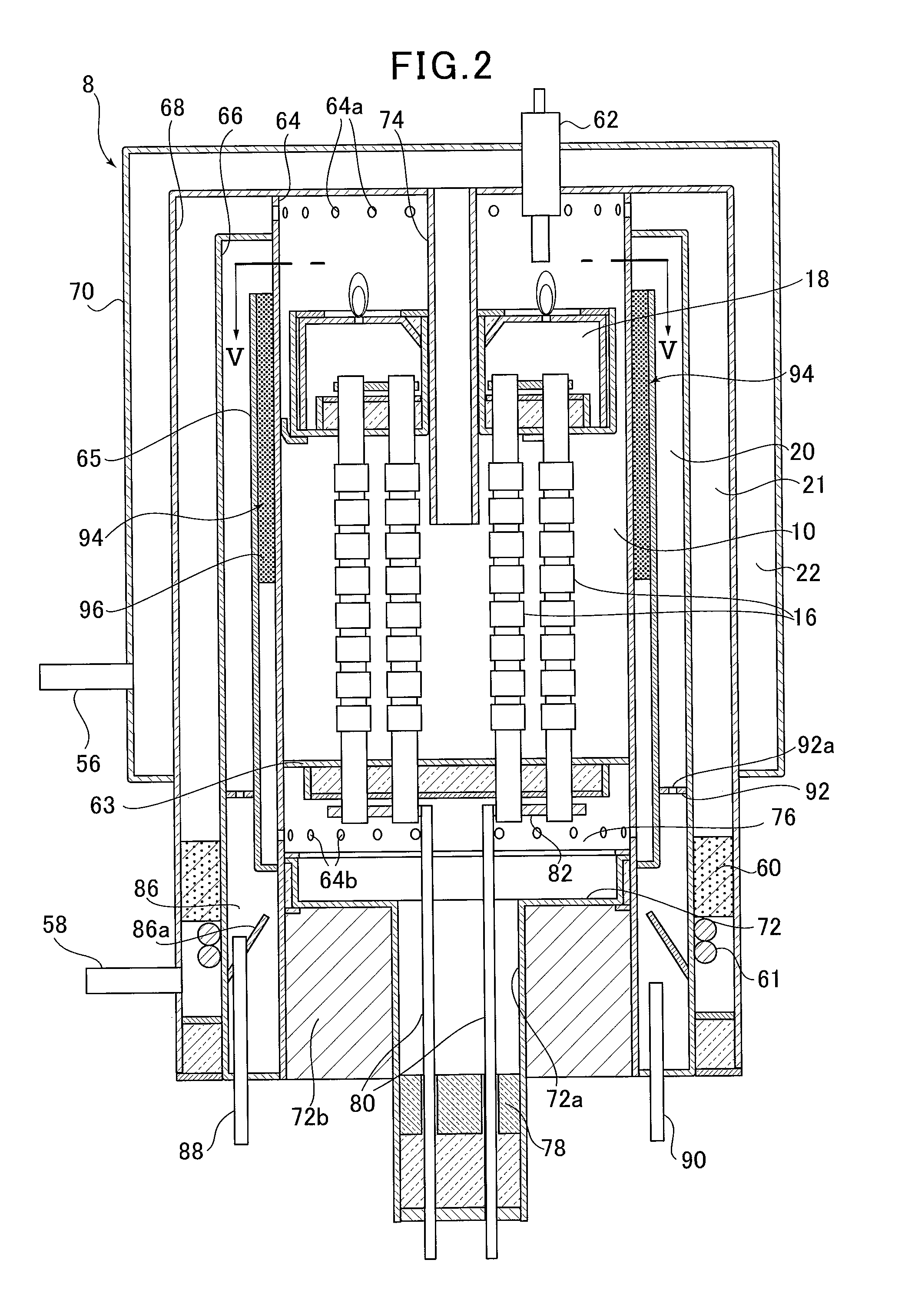
[0088]Next, referring to the attached drawings, we discuss a solid oxide fuel cell apparatus (SOFC) according to an embodiment of the present invention.

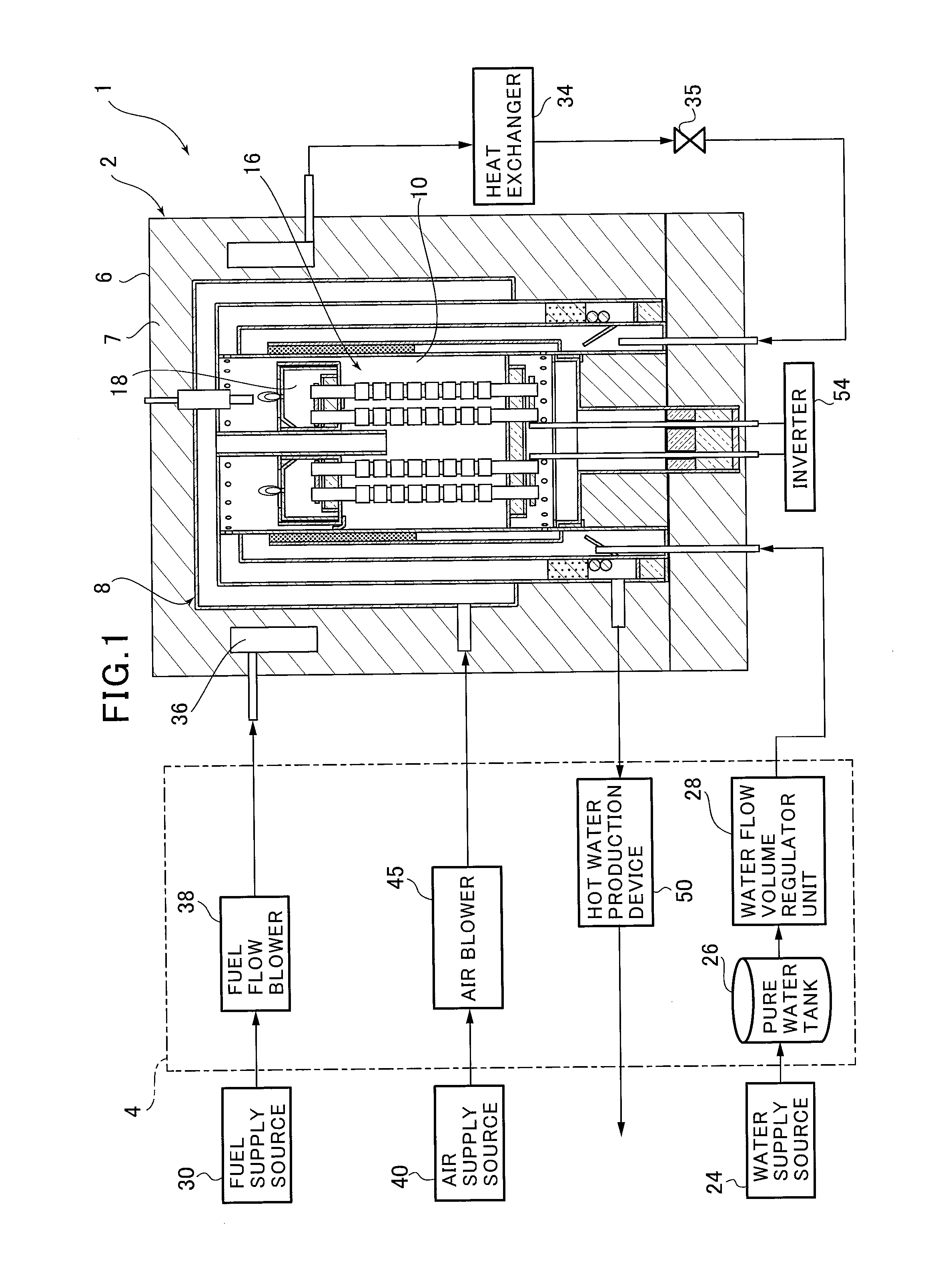
[0089]FIG. 1 is an overview diagram showing a solid oxide fuel cell (SOFC) apparatus according to an embodiment of the present invention. As shown in FIG. 1, the solid oxide fuel cell (SOFC) apparatus of this embodiment of the present invention is furnished with a fuel cell module 2 and an auxiliary unit 4.

[0090]Fuel cell module 2 comprises a fuel cell housing container 8; is formed within this housing 6, mediated by thermal insulation 7. A generating chamber 10 is formed on the interior of this fuel cell housing container 8; multiple fuel cells 16 are concentrically disposed within this generating chamber 10, and the generating reaction between fuel gas and air, which is the oxidizing gas, is carried out by these fuel cells 16.

[0091]An exhaust collection chamber 18 is attached to the top end of each individual fuel cell 16. Residual...


PUM

PropertyMeasurementUnit
temperatureaaaaaaaaaa
temperaturesaaaaaaaaaa

Abstract

The present invention is a method for manufacturing a solid oxide fuel cell apparatus for generating electricity by supplying fuel and oxidant gas to fuel cells housed in a fuel cell module, comprising: an adhesive application step for applying ceramic adhesive to the joint portions of constituent members so that the flow path carrying fuel or oxidant gas inside the fuel cell module are formed in an airtight manner; a workable hardening step for hardening the applied ceramic adhesive to a state capable of implementing the next manufacturing process; and a solvent elimination and hardening step wherein, after multiple repetitions of the adhesive application step and the workable hardening step, ceramic adhesive hardened in the workable hardening steps is dried to a state capable of withstanding temperatures during electrical generation.

Description

RELATED APPLICATIONS[0001]This application claims priority under 35 U.S.C. §119 to Japanese Patent Application Nos. 2013-135080 filed on Jun. 27, 2013 and 2013-135081 filed on Jun. 27, 2013, the entire contents of which are hereby incorporated by reference.BACKGROUND OF THE INVENTION[0002]1. Technical Field[0003]The invention pertains to a solid oxide fuel cell, and more particularly to a solid oxide fuel cell and manufacturing method and manufacturing apparatus for same.[0004]2. Background Art[0005]Solid oxide fuel cells (“SOFCs” below) are fuel cells which operate at a relatively high temperature in which, using an oxide ion-conducting solid electrolyte as electrolyte, with electrodes attached to both sides thereof, fuel gas is supplied to one side thereof and oxidant gas (air, oxygen, or the like) is supplied to the other side thereof.[0006]A fuel flow path for supplying fuel to fuel cells, and an oxidant gas flow path or the like for supplying oxidant gas such as air, are built ...

Claims


Application Information

Patent Timeline
Patent Type & Authority Applications(United States)
IPC IPC(8): H01M8/12H01M8/06H01M8/04H01M8/24
CPCH01M8/04089H01M8/12H01M2008/1293H01M8/0612H01M8/2465Y02E60/521Y02E60/525H01M8/0271H01M8/0282H01M8/0286H01M8/249Y02E60/50Y02P70/50
Inventor ISAKA, NOBUOWATANABE, NAOKITANAKA, SHUHEIHOSHIKO, TAKUYASATO, MASAKIOKAMOTO, OSAMUANDO, SHIGERUFURUYA, SEIKIMOMIYAMA, YUTAKAHAYAMA, KIYOSHI
Owner TOTO LTD
Why Eureka
Try Eureka