Aircraft galley air chiller system

Active Publication Date: 2015-01-08
BE AEROSPACE INCORPORATED
View PDF5 Cites 42 Cited by
  • Summary
  • Abstract
  • Description
  • Claims
  • Application Information

AI Technical Summary

Benefits of technology

[0004]The present invention is an aircraft chilled air distribution system with a reduced overall foot print and reduced weight, and with an improved overall heat transfer efficiency. This compact system is particularly well suited for an aircraft galley that requires refrigerated or cooled carts or trolleys, and/or carts carrying standard meal boxes, and/or chilled food and beverage compartments. The chiller system of the present invention uses a cooling unit adjacent the beverage carts and below the work deck of the aircraft galley, which includes ducting leading away from the beverage cart storage to carry away heated air during the cooling process. The chiller comprises a housing with a plurality of fans located preferably along an upper surface for drawing air into the unit to be introduced into a vapor cycle.

Problems solved by technology

One drawback of these various chiller systems is that they take up a large percentage of available space in the galley, which is at a premium in an aircraft for obvious reasons.
Further, the chiller

Method used


Image

  • Aircraft galley air chiller system
  • Aircraft galley air chiller system
  • Aircraft galley air chiller system

Examples


example 1

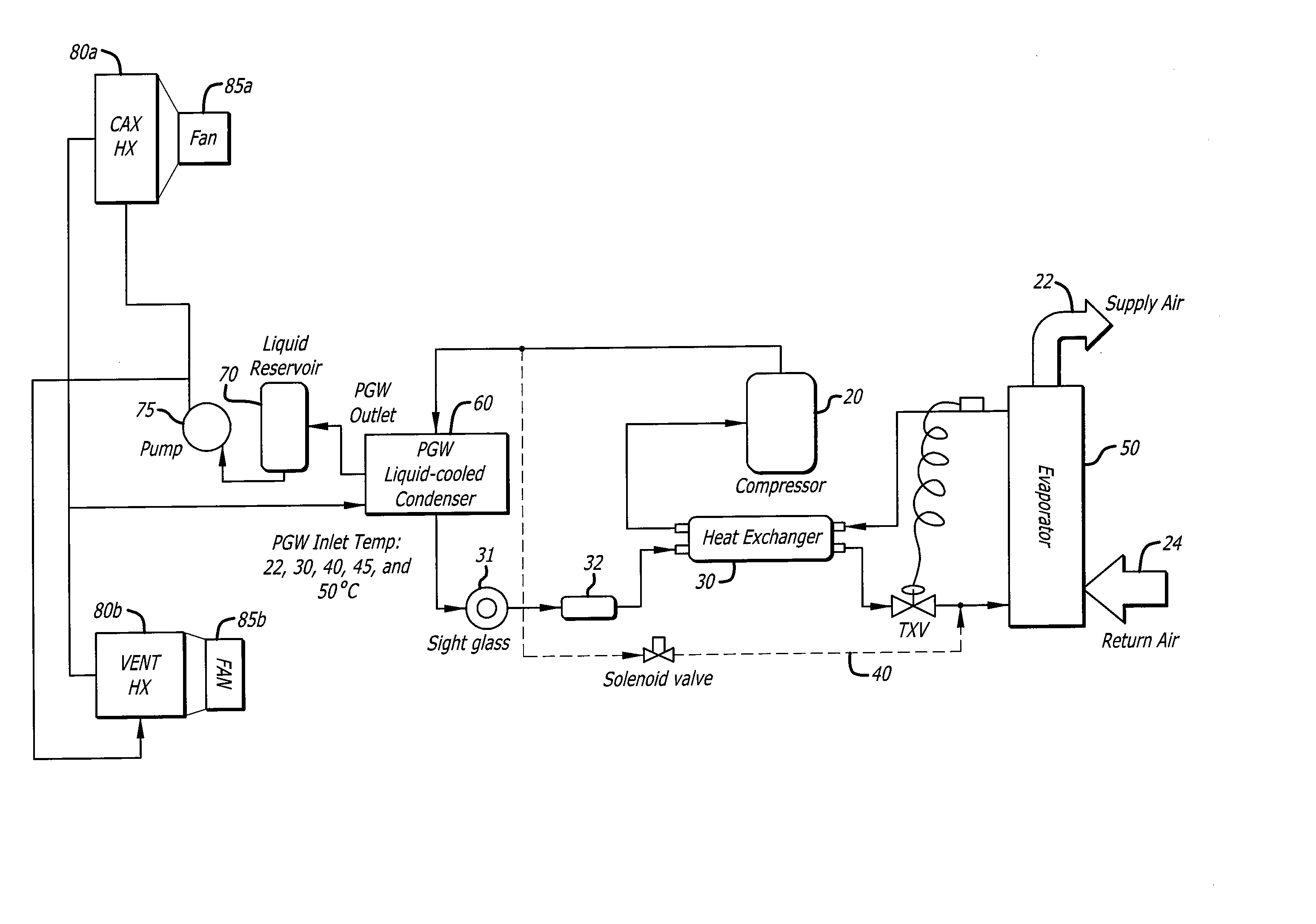
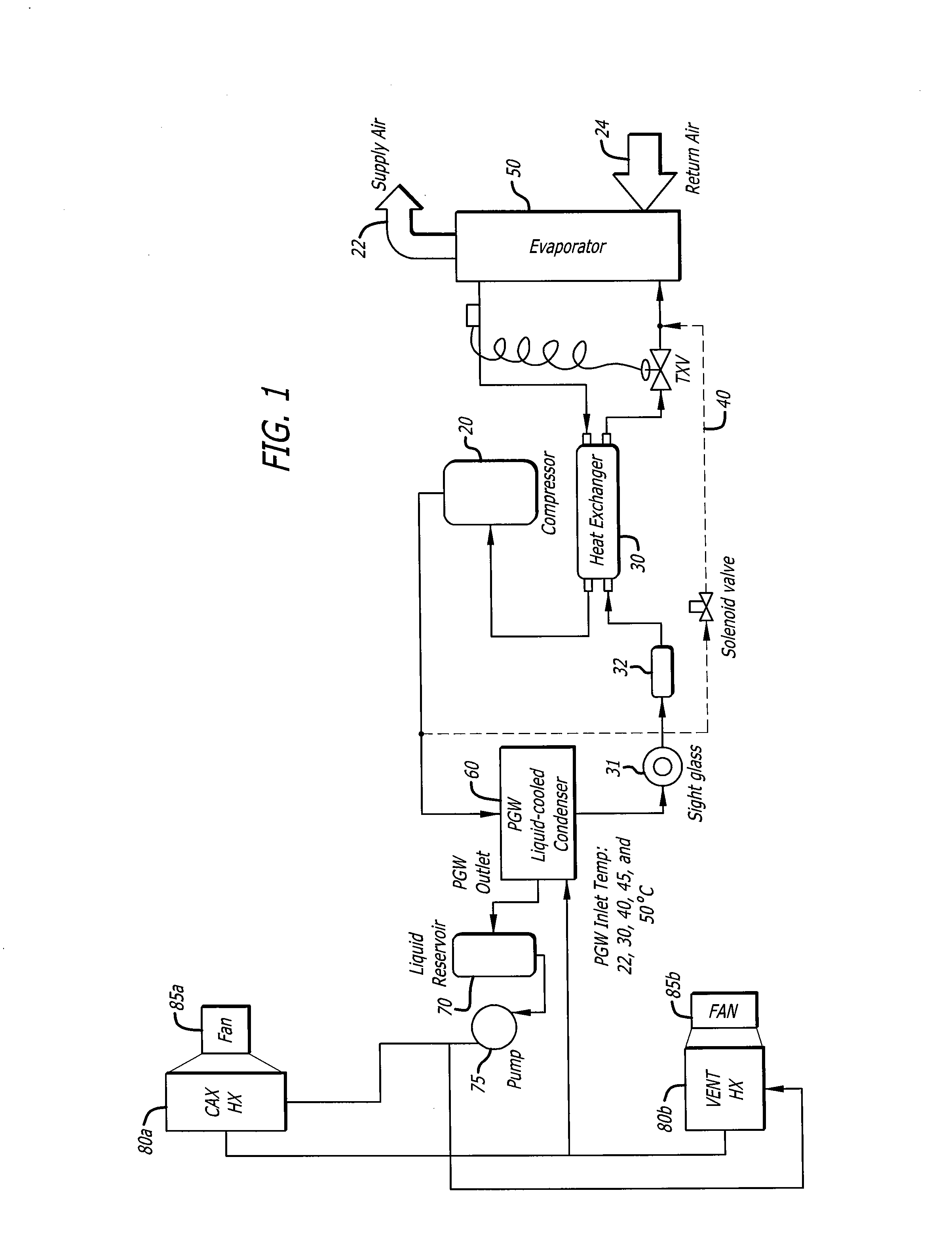
Liquid-Cooled Point of Use Chiller

[0016]Cooling capacity: 700 W (Ground case), and 300-400 W (In flight case)

[0017]Coolant: PGW (60 / 40)

[0018]Electronic controller with display panel.

Liquid Pump and Reservoir Assembly:

[0019]Liquid pump: 4 l / m with 50 Psi. pressure rise

[0020]Reservoir: Aluminum light weight design

Heat Exchanger 1

[0021]Located in aircraft CAX air system,

[0022]Maximum airflow: 40 l / s

[0023]Inlet temperature: 22° C. (in flight), and 29° C. (Ground, worst case)

[0024]Max. outlet air temperature: 70° C.

Heat Exchanger 2

[0025]Located in aircraft floor heater area,

[0026]Maximum airflow: 100 l / s

[0027]Inlet temperature: 22° C. (in flight), and 29° C. (Ground, worst case)

[0028]Max. outlet air temperature: 25° C.(to thermal comfort zone), 70° C. (to lower level)

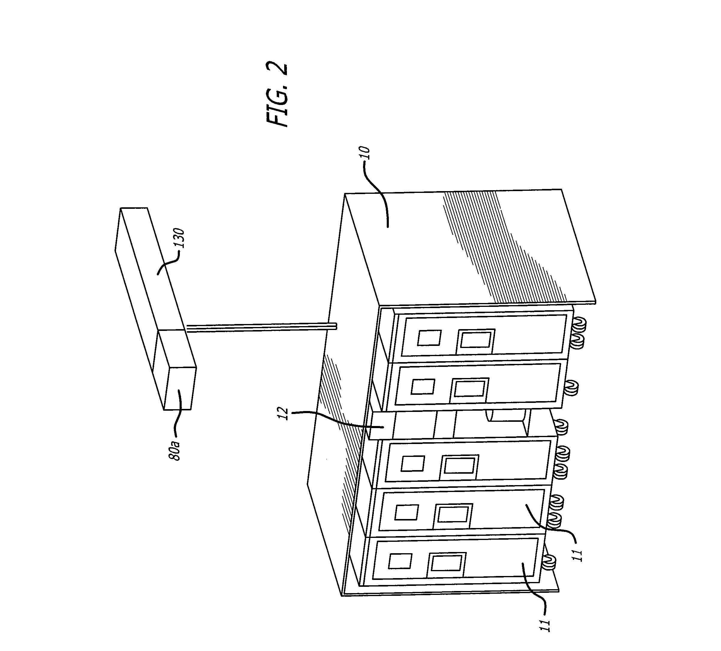
[0029]FIG. 2 illustrates a galley cart compartment 100 filled with beverage / serving carts 110 used in food and beverage service for an aircraft. The carts 110 are arranged side-by-side in the galley cart compartment 100, w...


PUM


Abstract

A chiller for an aircraft galley that is sized to be disposed in a compartment for housing beverage carts, the chiller comprising a vapor cycle refrigeration system with a liquid cooled condenser located within the housing and a liquid cooling unit located within the housing. Further, the vapor cycle refrigeration system and the liquid cooling unit have a combined footprint that is less than a footprint of a food and beverage cart within the housing, such that the space occupied by the chiller displaces no more than one beverage cart.

Description

BACKGROUND[0001]Large commercial passenger carrying airplanes predominantly employ one of two systems for keeping perishable food stuffs and non-perishable drinks at desired temperatures. Chilling is necessary to preserve perishables and make certain beverages and foods more palatable, especially during long haul and ultra-long haul aircraft journeys. The first method utilizes a standard vapor cycle based air chillers that utilize conventional refrigerant gas compression and expansion technology to generate a secondary re-circulated chilled air loop. The chilled air is generally supplied and returned via thermally insulated air ducting to and from a suitable storage structure, such as a galley. The air chiller may be located on or in the galley or mounted in part of the aircraft airframe.[0002]The second method utilizes the same conventional refrigerant gas compression and expansion technology, but the cooling medium is a chilled liquid rather than a gas. This chilled liquid is pump...

Claims


Application Information

Patent Timeline
IPC IPC(8): B64D11/04F25D17/06F25B29/00
CPCB64D11/04F25D17/06F25B29/003B64D2013/0629F25D2400/20F25D19/00F25B2339/047F25D17/02Y02T50/40
Inventor GODECKER, WILLIAM J.LU, QIAOTRUMPER, TORTSTEN
Owner BE AEROSPACE INCORPORATED
Why Eureka
Try Eureka