
MEMS pressure sensors and fabrication method thereof

a technology of pressure sensors and manufacturing methods, applied in the direction of fluid pressure measurement, fluid pressure measurement by electric/magnetic elements, instruments, etc., can solve the problems of inability to meet the requirements of continuous technology development, and the sensitivity of the capacitive structure may have a certain limitation

Active Publication Date: 2015-01-08
SEMICON MFG INT (SHANGHAI) CORP
View PDF7 Cites 15 Cited by
  • Summary
  • Abstract
  • Description
  • Claims
  • Application Information

AI Technical Summary

Benefits of technology

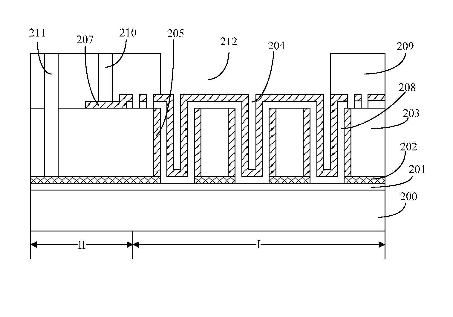
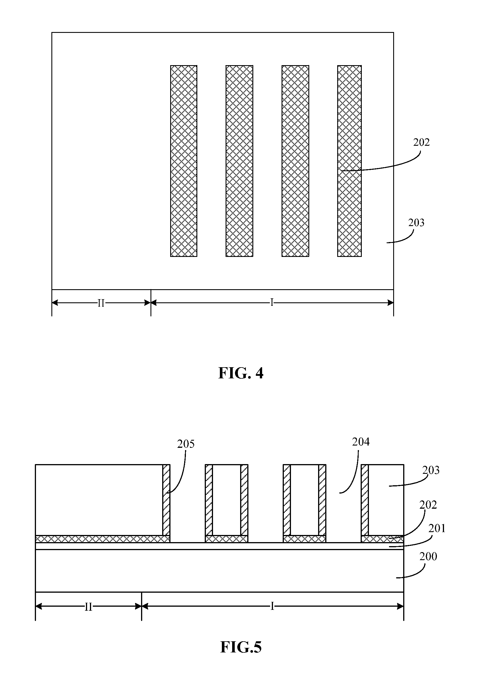
The patent proposes a capacitive structure for a pressure sensor with improved sensibility. The structure includes a second conductive layer that has concave depressions towards the openings in the first dielectric layer. This results in a more uniform pressure distribution and significant deformation of the second electrode layer under pressure. The first openings have a width ranging from 3000 Å to 10 μm to prevent filling them up with the subsequent layers. The capacitive structure formed by the first openings has a significantly large capacitive change and improved sensibility to pressure. The text also mentions that the structure can be easily formed using simple patterns and strips.

Problems solved by technology

However, the sensibility of the capacitive structure may have a certain limitation, and may be unable to match requirements of continuous technology developments.

Method used


Image

  • MEMS pressure sensors and fabrication method thereof
  • MEMS pressure sensors and fabrication method thereof
  • MEMS pressure sensors and fabrication method thereof

Examples


Embodiment Construction

[0013]Reference will now be made in detail to exemplary embodiments of the invention, which are illustrated in the accompanying drawings. Wherever possible, the same reference numbers will be used throughout the drawings to refer to the same or like parts.

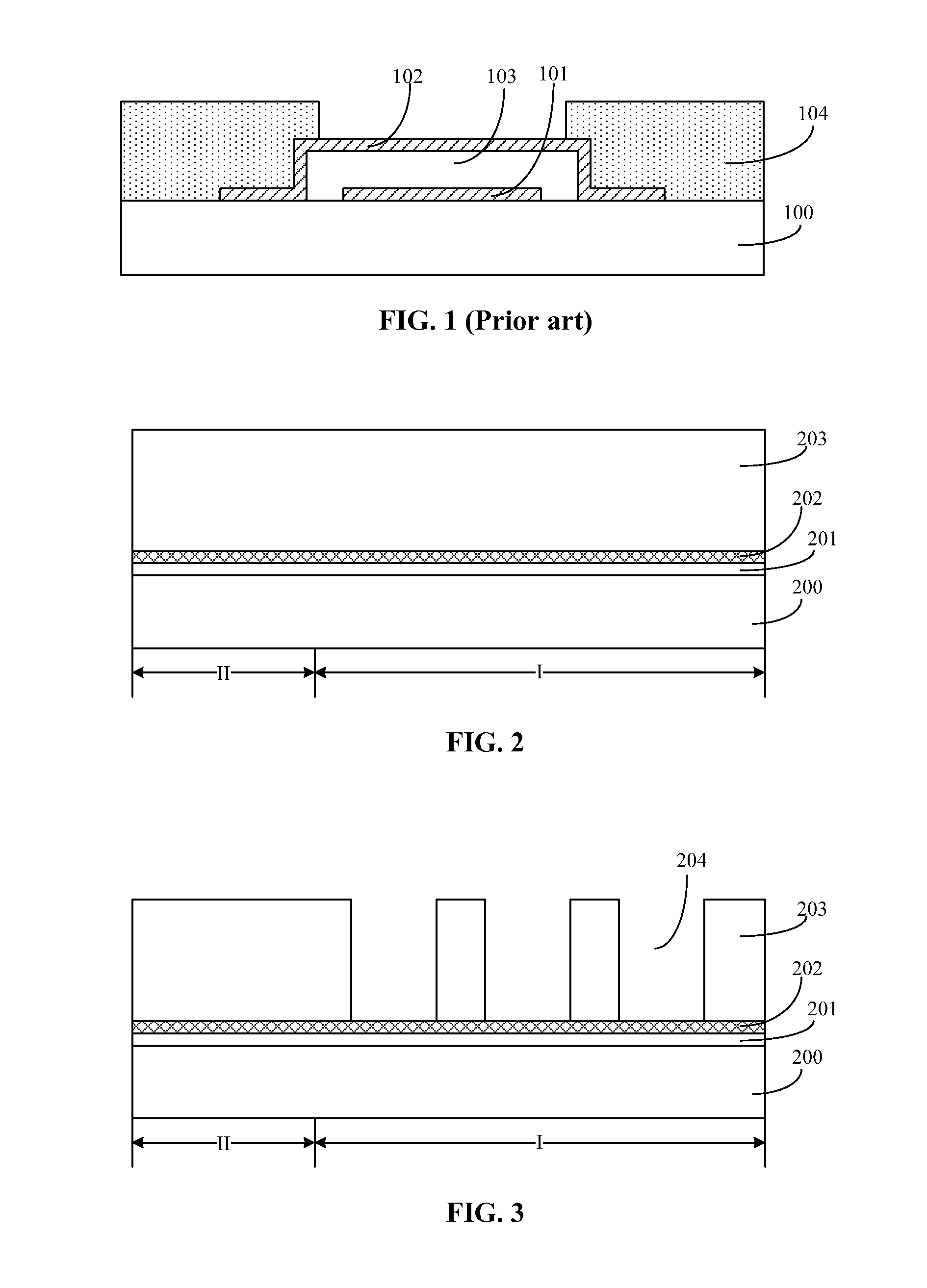
[0014]Referring to FIG. 1, when the MEMS capacitive pressure sensor converts the pressure applied on the second electrode layer 102 into an electrical output signal of the capacitive structure, the capacitance of the capacitive structure is reversely proportional to the distance between the first electrode layer 101 and the second electrode layer 102. The capacitance of the capacitive structure is also proportional to an overlap area of the first electrode layer 101 and the second electrode layer 102.

[0015]However, size of such a MEMS capacitive pressure sensor may be limited by a chip size and / or sizes of semiconductor devices; and the overlap area between the first electrode layer 101 and the second electrode layer 102 may also b...


PUM

PropertyMeasurementUnit
dielectric constantaaaaaaaaaa
pressureaaaaaaaaaa
temperatureaaaaaaaaaa

Abstract

A MEMS capacitive pressure sensor is provided. The pressure sensor includes a substrate having a first region and a second region, and a first dielectric layer formed on the substrate. The pressure sensor also includes a first electrode layer formed on the first dielectric layer, and a second dielectric layer having first openings formed on the first electrode layer. Further, the pressure sensor includes conductive sidewalls connecting with the first electrode layer formed on sidewalls of the first openings, and a second electrode layer with a portion formed on the second dielectric layer in the second region and the rest suspended over the conductive sidewalls in the first region. Further, the pressure sensor also includes a chamber between the conductive sidewalls and the second electrode layer; and a third dielectric layer formed on the second electrode layer exposing a portion of the second electrode layer in the first region.

Description

CROSS-REFERENCES TO RELATED APPLICATIONS[0001]This application claims the priority of Chinese patent application No. 201310277644.0, filed on Jul. 3, 2013, the entirety of which is incorporated herein by reference.FIELD OF THE INVENTION[0002]The present invention generally relates to the field of semiconductor manufacturing technology and, more particularly, relates to pressure sensors and fabrication techniques thereof.BACKGROUND[0003]Micro-electro-mechanical system (MEMS) is an integrated device which can obtain information; perform information processing; and execute operations. A MEMS sensor can detect various external information including pressure, position, velocity, acceleration, magnetic field, temperature or humidity, etc; and convert these external information into electrical signals. Thus, these external information can be processed by the MEMS. A pressure sensor is a device that can convert pressure signals into electric signals; and a MEMS capacitive sensor is a typica...

Claims


Application Information

Patent Timeline
Patent Type & Authority Applications(United States)
IPC IPC(8): B81B3/00B81C1/00
CPCB81B3/0021B81C1/00182B81C1/00166B81B2201/0264B81B2203/0392B81B2203/04G01L9/0073B81B7/007
Inventor HONG, ZHONGSHAN
Owner SEMICON MFG INT (SHANGHAI) CORP
Learn More