Processing of metal or alloy objects

a technology of metal or alloy objects and processing equipment, applied in the field of objects, can solve problems such as adversely affecting the fatigue performance of objects, and achieve the effect of reducing the size of the closed cavity

Inactive Publication Date: 2015-01-15
WARD CLOSE CHARLES MALCOLM
View PDF2 Cites 22 Cited by
  • Summary
  • Abstract
  • Description
  • Claims
  • Application Information

AI Technical Summary

Benefits of technology

[0007]In a first aspect, the present invention provides a method of processing an object, the object being made of a metal or an alloy, the object having a plurality of open cavities, the method comprising performing a sealing process on the object to seal the openings of the open cavities, thereby forming a plurality of closed cavities, and reducing the sizes of the closed cavities by performing a consolidation process on the object having the closed cavities.

Problems solved by technology

However, such manufactured objects, particularly those made by powder metallurgy processes, may comprise micro-pores and other imperfections at or proximate to the surface of the object.
The presence of such imperfections tends to adversely affect the fatigue performance of an object, especially in high-cycle fatigue situations.

Method used


Image

  • Processing of metal or alloy objects
  • Processing of metal or alloy objects
  • Processing of metal or alloy objects

Examples


first embodiment

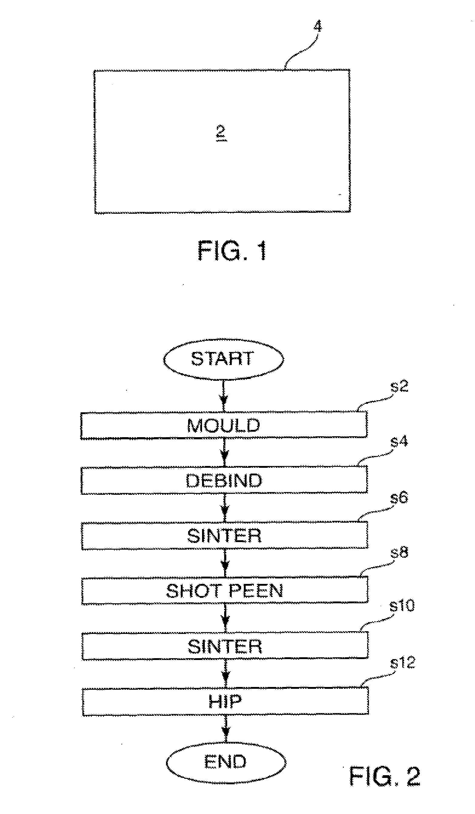
[0035]FIG. 1 is a schematic illustration (not to scale) of an object 2. The object 2 is made of a titanium alloy. The object 2 may be any appropriate object e.g. a component part of a machine or machinery. The object has a surface 4. a process of producing the object 2 will now be described.

[0036]FIG. 2 is a process flow chart showing certain steps of a first embodiment of a process of producing the object 2.

[0037]At step s2, a metal injection moulding process is performed to produce a so-called “green part”.

[0038]In this embodiment, a conventional metal injection moulding process is performed. A relatively finely-powdered alloy is mixed with binder material to produce a so called “feedstock”. This feedstock is shaped using an injection mould process to produce the green part.

[0039]In this embodiment, the alloy is titanium with 6% aluminium and 4% vanadium (also known as Ti-6Al-4V, or 6-4, 6 / 4, ASTM B348 Grade 5).

[0040]At step s4, after the green part is cooled and de-moulded, a por...

second embodiment

[0071]FIG. 7 is a process flow chart showing certain steps of a process of producing the object 2.

[0072]At step s14, a metal injection moulding process is performed to produce a green part. This is done as described above with reference to step s2 of FIG. 2.

[0073]At step s16, a portion of the binder material is removed from the green part to produce a brown part. This is done as described above with reference to step s4 of FIG. 2.

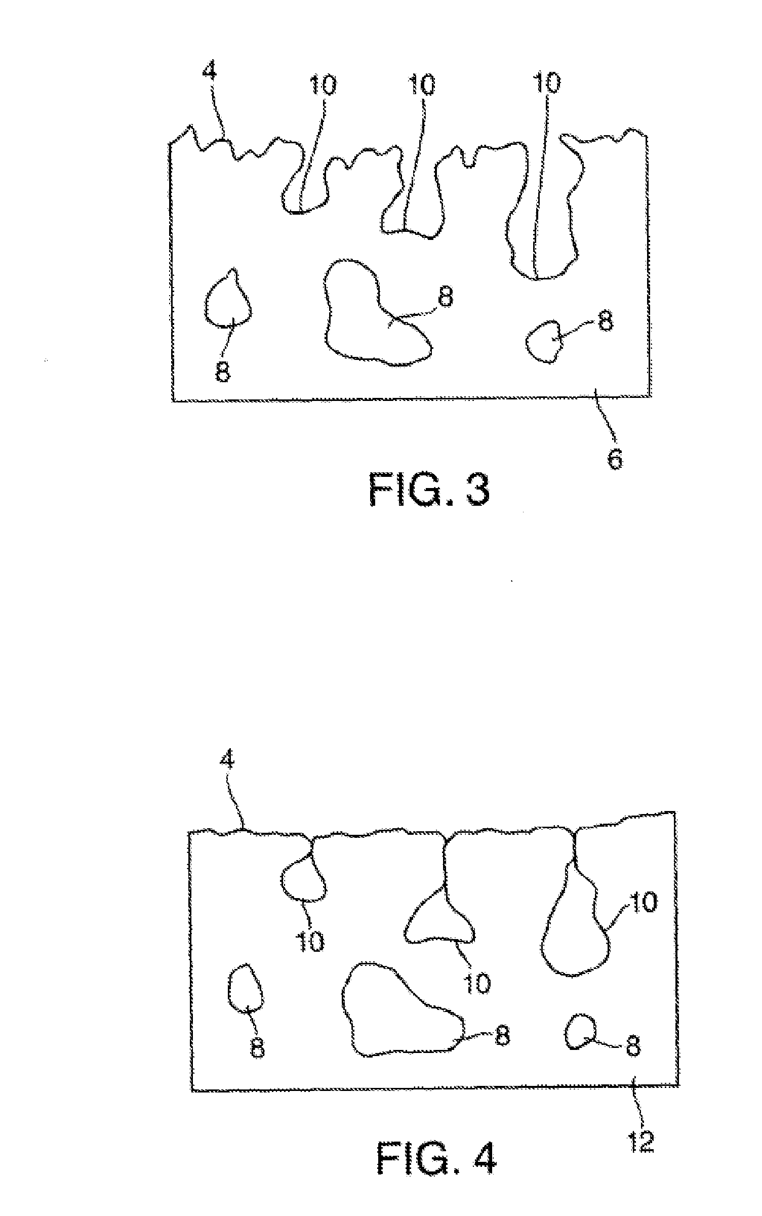
[0074]At step s18, a sintering process is performed on the brown part to produce a sintered part 6. This is done as described above with reference to step s6 of FIG. 2.

[0075]The sintered part 6 at step s18 is as described above with reference to FIG. 3.

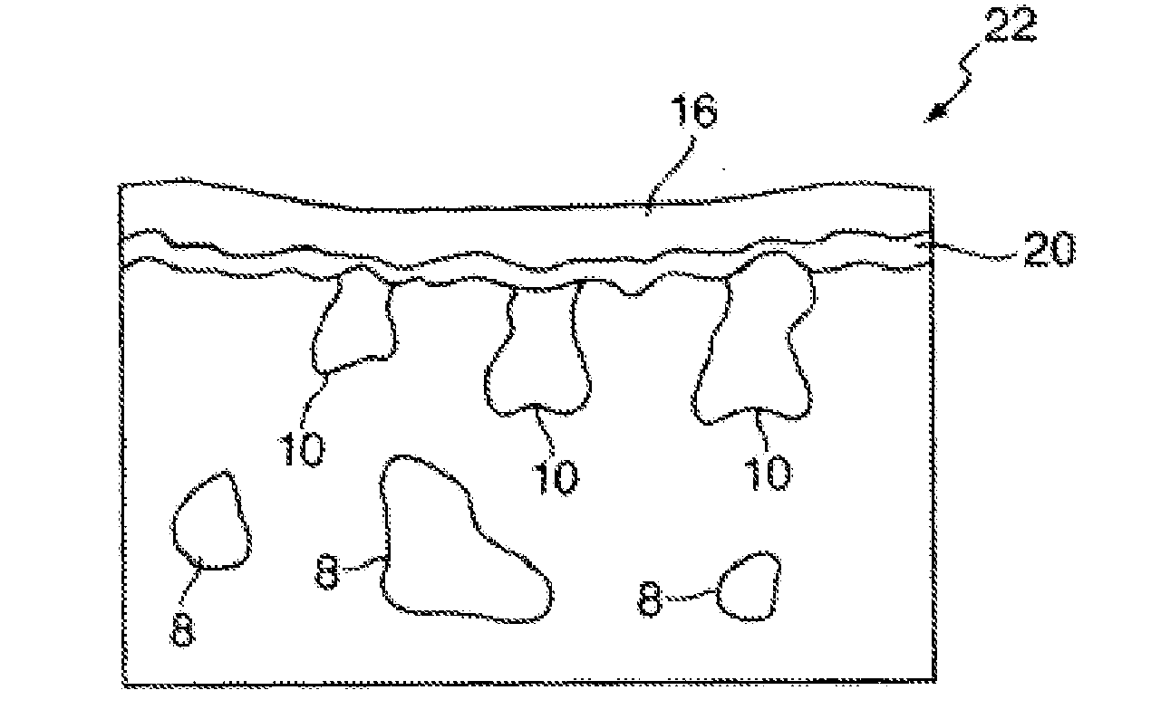
[0076]At step s20, the surface 4 of the sintered part 6 is coated, or plated, with a layer of copper.

[0077]The coating of the surface of the sintered part 6 may be performed using any appropriate coating or plating process, for example electro-plating.

[0078]FIG. 8 is a schematic illustration (not to scale) of...


PUM

PropertyMeasurementUnit
temperatureaaaaaaaaaa
surface roughnessaaaaaaaaaa

Abstract

Disclosed are methods of processing an object, the object being made of a metal or an alloy, the object having a plurality of open cavities, the method comprising: performing a sealing process on the object to seal the openings of the open cavities, thereby forming a plurality of closed cavities; and reducing the sizes of the closed cavities by performing a consolidation process on the object having the closed cavities. Sealing process may comprise shot peening or coating the object. A consolidation process may comprise a hot isostatic pressing process. The sizes of the closed cavities may be reduced until the closed cavities are no longer present in the object.

Description

CROSS-REFERENCE TO RELATED APPLICATION[0001]This application is the National Stage of International Application No. PCT / GB2013 / 050409, filed 20 Feb. 2013, which claims the benefit of and priority to GB 1203359.3, filed 24 Feb. 2012, the contents of all of which are incorporated by reference as if fully set forth herein.FIELD OF THE INVENTION[0002]The present invention relates to the processing of objects, in particular objects made of metals or alloys.BACKGROUND[0003]Metals and metal alloys are used in many market sectors, including the aerospace, medical and sports and leisure sectors.[0004]The manufacture of metal or alloy objects may be performed by machining processes or a combination of forging and machining processes. Objects may also be made using casting and / or powder metallurgy routes, for example using a metal injection moulding process.[0005]However, such manufactured objects, particularly those made by powder metallurgy processes, may comprise micro-pores and other imper...

Claims


Application Information

Patent Timeline
Patent Type & Authority Applications(United States)
IPC IPC(8): B23K20/00B23K20/02B32B15/01
CPCB23K20/227B23K20/002B23K2201/00B23K20/02B23K20/233B32B15/01Y10T428/12806B23K20/2333B22F3/1035B22F3/15B22F3/168B22F3/24B22F2003/248B33Y70/00B23K2101/00Y02P10/25B22F10/28B22F10/66B22F10/62B22F10/64B22F10/25B22F3/16B23P6/00B22D31/005C21D8/00C22C1/00C23C10/28C23C10/60C25D5/50B22F10/00B22F3/003B22F3/02B22F3/1039
Inventor WARD-CLOSE, CHARLES MALCOLM
Owner WARD CLOSE CHARLES MALCOLM
Why Eureka
Try Eureka