Low resistance insert

a low-resistance, insert technology, applied in the direction of connection contact material, cable termination, connection device connection, etc., can solve the problems of affecting the bonding performance of the metal gasket, the breakdown of inhibitors, and the limited methods of providing coupling between mating surfaces in aircraft having aluminum structures, etc., to achieve the effect of low bonding resistan

Active Publication Date: 2015-02-12
TYCO ELECTRONICS LOGISTICS AG (CH)
View PDF44 Cites 18 Cited by
  • Summary
  • Abstract
  • Description
  • Claims
  • Application Information

AI Technical Summary

Benefits of technology

[0006]An embodiment is directed to an insert which can be used with aluminum terminals which are intended for use with composite structure aircra

Problems solved by technology

Known methods of providing coupling between mating surfaces in aircraft having aluminum structures are generally limited to the uses of cured elastomer gaskets, metallic gaskets using sealants, or a multiple use of corrosion inhibitors and plating.
The metallic gaskets also have a permanent bonding problem due to the application of adhesives to reduce the moisture ingress between the two surfaces.
The use of the corrosion resistant compounds and sealants creates a time consuming process in application and removal and tend to crack during s

Method used


Image

  • Low resistance insert
  • Low resistance insert
  • Low resistance insert

Examples


Embodiment Construction

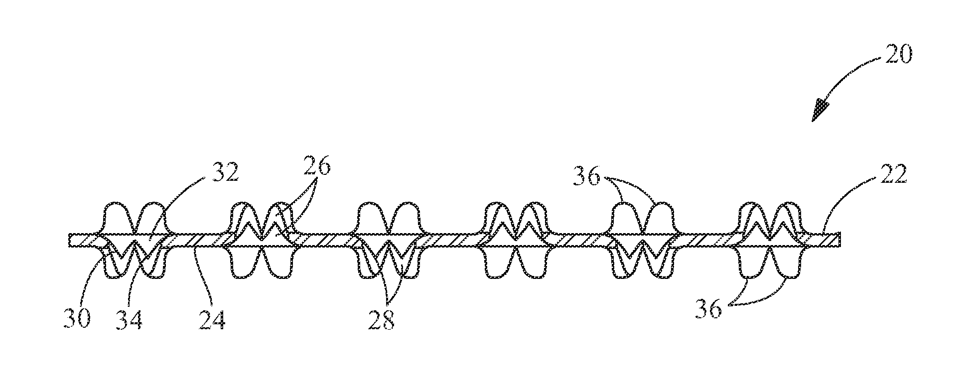
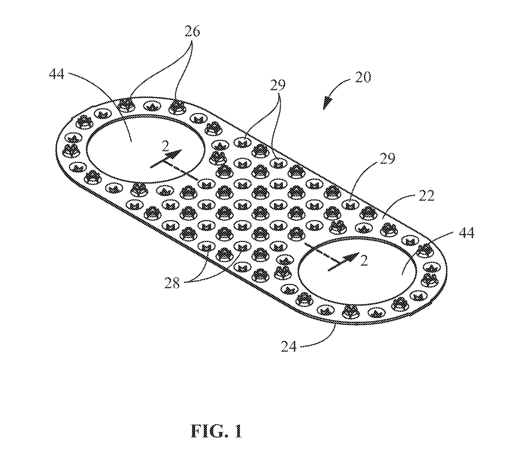
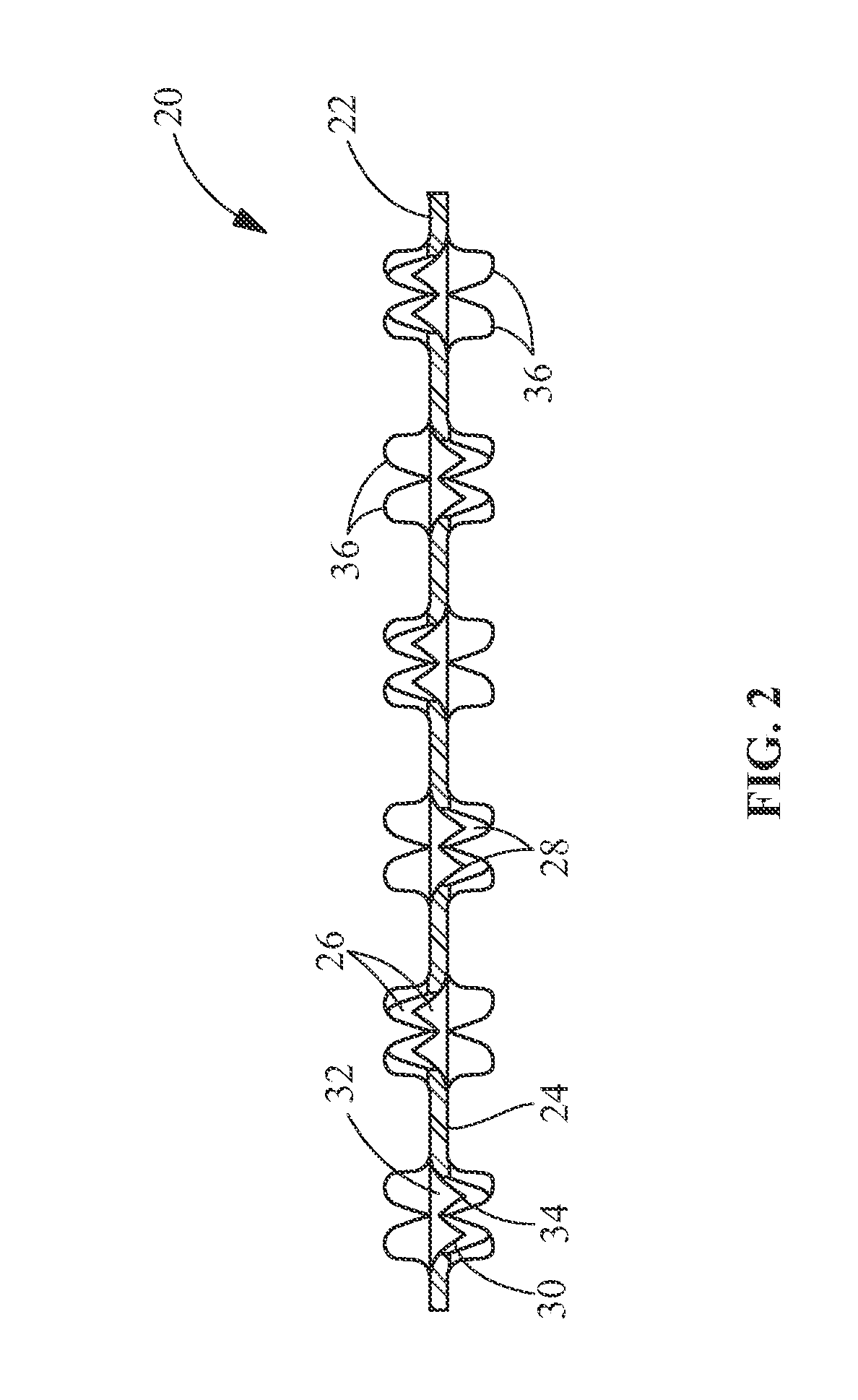
[0016]The present invention will be described more fully hereinafter with reference to the accompanying drawings, in which illustrative embodiments of the invention are shown. In the drawings, the relative sizes of regions or features may be exaggerated for clarity. This invention may, however, be embodied in many different forms and should not be construed as limited to the embodiments set forth herein; rather, these embodiments are provided so that this disclosure will be thorough and complete, and will fully convey the scope of the invention to those skilled in the art.

[0017]It will be understood that spatially relative terms, such as “top”, “upper”, “lower” and the like, may be used herein for ease of description to describe one element's or feature's relationship to another element(s) or feature(s) as illustrated in the figures. It will be understood that the spatially relative terms are intended to encompass different orientations of the device in use or operation in addition ...


PUM


Abstract

A conductive insert which provides a low resistance bond between low conductive materials. The insert includes a first surface and an oppositely facing second surface. A plurality of openings extends between the first surface and the second surface. At least one first projection extends from the first surface proximate respective first openings, the at least one first projections extend from the first surface in a direction away from the second surface. At least one second projection extends from the second surface proximate respective second openings, the at least one second projections extend from the second surface in a direction away from the first surface. The insert provides a stable, low resistance electrically conductive path between the conductive materials.

Description

FIELD OF THE INVENTION[0001]The present invention is directed to a conductive insert which provides a low resistance bond between low conductive materials. In particular, the invention is directed to an insert or screen which cooperates with light weight material, such as aluminum, to break through any sealant and / or aluminum oxide provided on the surface.BACKGROUND OF THE INVENTION[0002]A need has been identified in many industries to reduce the weight of products by reducing the weight of the components by utilizing lighter weight materials. As an example, the airline industry desires to reduce the weight of the aircraft, thereby reducing the fuel consumption, which in turn, reduces cost. This can be achieved, in part, by replacing the base metal in copper terminals with lighter weight material such as aluminum. This need follows the change from copper wire to aluminum wire on aircraft. However, prior to converting the terminals to a lighter weight material, it must be confirmed t...

Claims


Application Information

Patent Timeline
IPC IPC(8): H01B5/00H01B1/02
CPCH01B1/023H01B5/00B64D45/02F16J15/064H01R4/06H01R4/26H01R4/34H01R4/62H01R11/12H01R13/533
Inventor DEBOCK, KIMBERLYFABIAN, DAVID JAMESKLINGER, BRIAN TODD
Owner TYCO ELECTRONICS LOGISTICS AG (CH)
Why Eureka
Try Eureka