
Engine noise attenuation

Active Publication Date: 2015-03-12
FORD GLOBAL TECH LLC
View PDF17 Cites 4 Cited by
  • Summary
  • Abstract
  • Description
  • Claims
  • Application Information

AI Technical Summary

Benefits of technology

The patent text describes various ways to reduce noise in engine systems. One method involves using an inlet silencer to attenuate the sound waves produced as air accelerates into the compressor. Another method involves adding a noise attenuator to the clean side air duct, which can be positioned at an area of concentrated noise. The surfaces of the attenuator are directed inward and form a smooth path for sound waves to travel inward and minimize noise emitted from the engine. The design of the noise attenuator can be optimized for different engines and vehicle lines to provide smooth, even, and gradual air flow and reduce resistance for air induction system performance and engine performance. Overall, various embodiments describe methods to reduce noise in engine systems in a cost-effective, simple way.

Problems solved by technology

In the absence of special noise reduction treatment, loud, objectionable, harsh, and unwanted noise from engine combustion may travel thru the air induction system and may egress from the avenue(s) of air ingress.
In this way, at least one path along which noise may travel from the engine may be made “rough” and may be otherwise more disruptive to sound waves that may be emitted from the engine.
In this way a “rough” path which may be disruptive to the sound waves may make it more difficult for sound waves to travel from the engine and out through the induction passage.

Method used


Image

  • Engine noise attenuation
  • Engine noise attenuation
  • Engine noise attenuation

Examples


Embodiment Construction

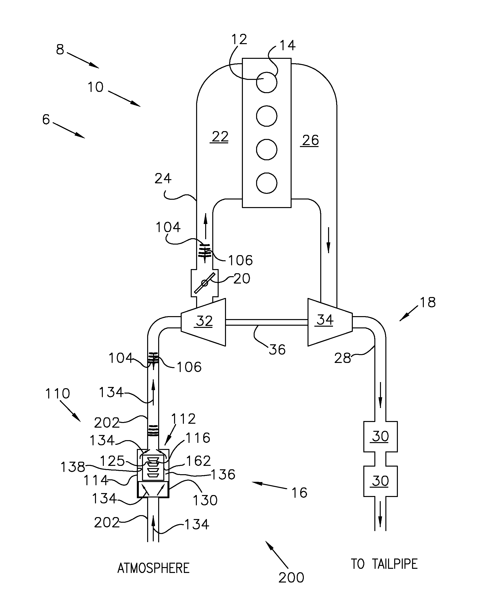
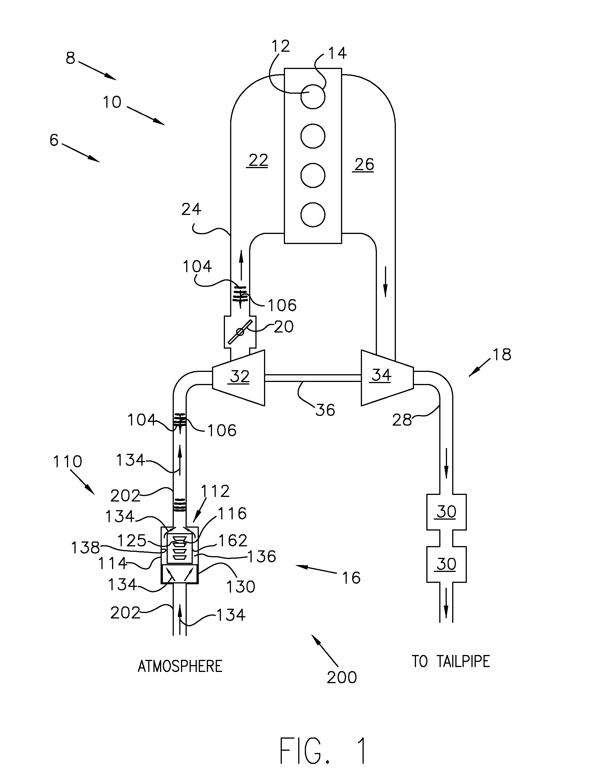
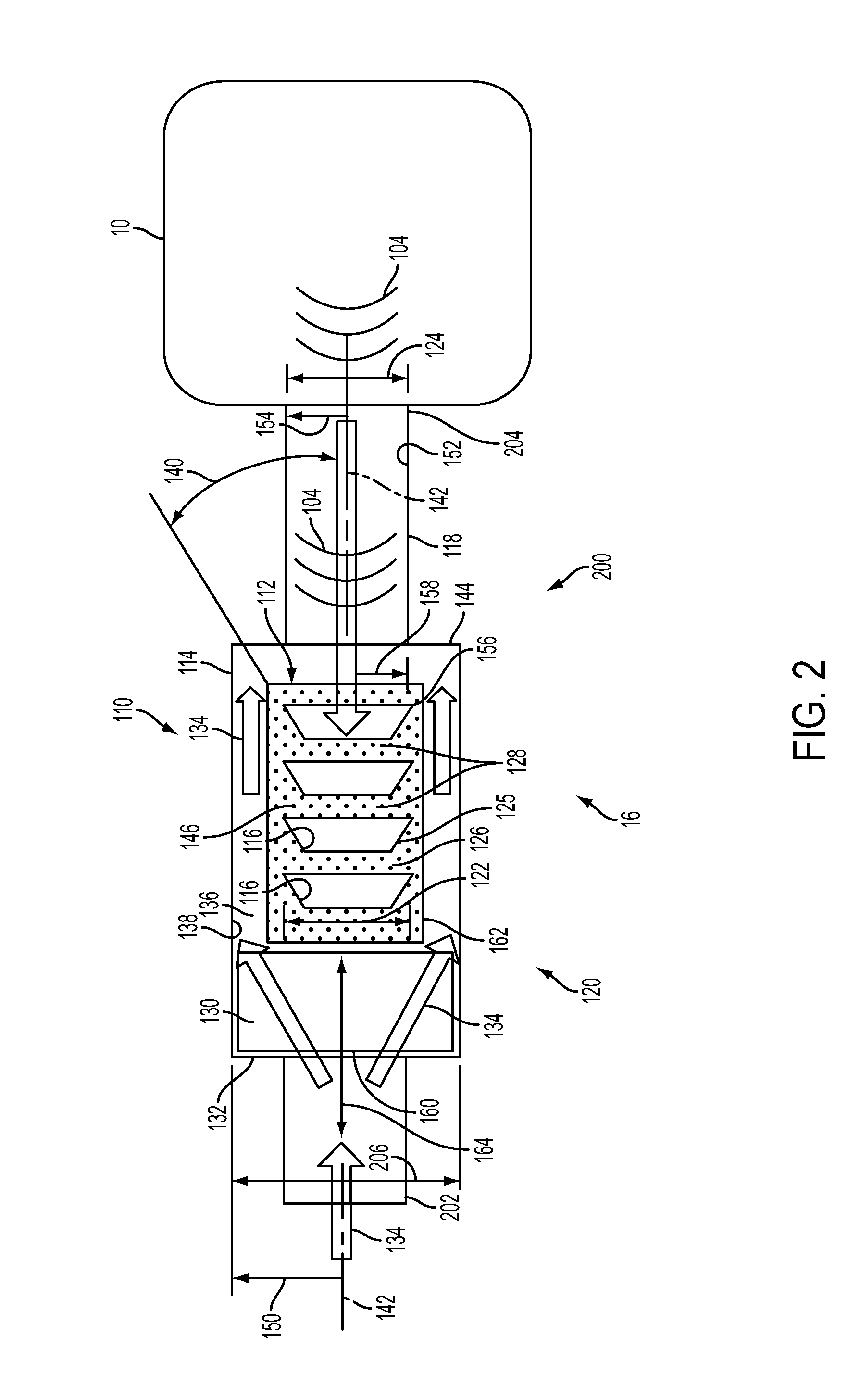
[0020]FIG. 1 illustrates a schematic depiction of an engine system including an example induction passage noise attenuator, and system in accordance with the present disclosure. FIG. 2 is a sectional side view of an example induction passage noise attenuator that may be used with the engine system illustrate in FIG. 1. The vehicle system 6 may include an engine system 8. The engine system 8 may include an engine 10 having a plurality of cylinders 12 defining a respective plurality of combustion chambers 14. The engine 10 may include an engine intake, or intake passage 16, and an engine exhaust 18. The engine intake 16 may include a throttle 20 fluidly coupled to an engine intake manifold 22 via an intake passage 24 to regular intake air flow. The engine exhaust 18 may include an exhaust manifold 26 leading to an exhaust passage 28 that routes exhaust gas to the atmosphere via a tailpipe. The engine exhaust passage 28 may include one or more emission control devices 30, which may be ...


PUM


Abstract

An induction passage noise attenuator and a system are provided. The induction passage noise attenuator may include a series of surfaces arranged within an enclosure upstream from a clean side air duct on an induction inlet for an internal combustion engine. Each surface of the series of surfaces may have a diametric extent being substantially in line with an inner diameter of the clean side air duct.

Description

TECHNICAL FIELD[0001]The present application relates to a device and a system for reducing a level of internal combustion engine noise audible through the engine's induction air system.BACKGROUND AND SUMMARY[0002]In the absence of special noise reduction treatment, loud, objectionable, harsh, and unwanted noise from engine combustion may travel thru the air induction system and may egress from the avenue(s) of air ingress.[0003]Efforts have been made to reduce the levels of audible noises from various engine systems. For example, the noises produced from the flow of induction air flowing through an induction passage and through a turbo compressor on its way to the engine combustion chamber(s) are often addressed by fitting an inlet silencer to the compressor wheel inlet to attenuate the sound waves produced as air accelerates into the compressor. U.S. Pat. No. 6,736,238 provides an air intake silencer configured to reduce turbulence in the air flow from the silencer to the intake of...

Claims


Application Information

Patent Timeline
IPC IPC(8): F02M35/12
CPCF02M35/12F02M35/14F02K1/827F05D2220/40F02M35/1211F02M35/1272F01N1/089F01N13/007F01N1/02F02M35/1233F02M35/10295F02M35/1255
Inventor MCCURE, RANDALL PAUL
Owner FORD GLOBAL TECH LLC
Learn More