Angiographic Examination Method for a Vascular System

a vascular system and angiography technology, applied in the field of angiography, can solve the problems of incongruity in navigation, inaccuracy or incongruity in overlay,

Active Publication Date: 2015-04-02
SIEMENS HEALTHCARE GMBH
View PDF11 Cites 19 Cited by
  • Summary
  • Abstract
  • Description
  • Claims
  • Application Information

AI Technical Summary

Benefits of technology

[0027]Thanks to this 3D correction of the overlay images because the 3D position of the inserted instrument is identified from only one X-ray projection, the displacements arising because of the insertion of instruments may essentially be eliminated automatically.

Problems solved by technology

A problem with these overlays is that the reference image (2D or 3D) shows the vascular anatomy at a particular point in time.
If this deformation is not corrected in the overlaid reference image, this produces an inaccuracy or “incongruity” in the overlay, as further explained below.
This may result in uncertainties in the navigation during a subsequent intervention, in which the overlay serves as an aid to navigation.

Method used


Image

  • Angiographic Examination Method for a Vascular System
  • Angiographic Examination Method for a Vascular System
  • Angiographic Examination Method for a Vascular System

Examples


Embodiment Construction

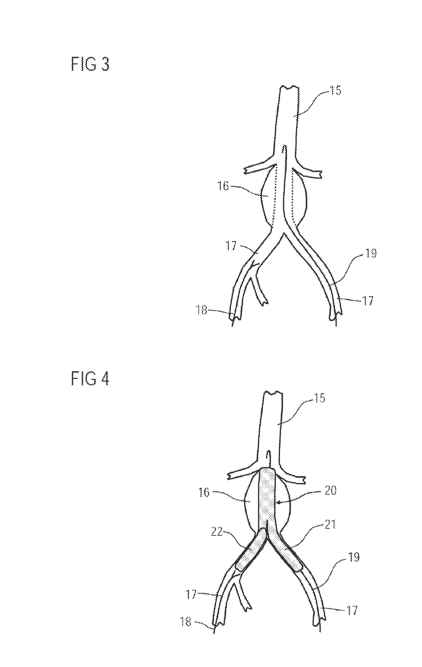
[0055]FIG. 3 illustrates an abdominal aorta 15 that has an abdominal aortic aneurysm (AAA) 16. An AAA 16 is a vascular dilatation on the abdominal aorta 15. The aorta 15 branches into femoral arteries 17 (e.g., arteria iliaca communis).

[0056]The aortic aneurysm 16 is treated by inserting a stent graft (e.g., a composite vascular stent), as illustrated in FIG. 4. Guide wires 18 and catheters 19, by which stent grafts 20 are inserted, are inserted into the aorta 15 through the femoral arteries 17 by way of both groins.

[0057]In the case of complex stent grafts 20 that also encompass the femoral arteries 17, a final stent may be composed of “part-stents.” For example, an iliacal stent 22, as a part-stent for the other femoral artery 17, is to be “flange-mounted” onto an aortic stent 21 as a main stent, which projects through the AAA into one of the femoral arteries 17, through a so-called window.

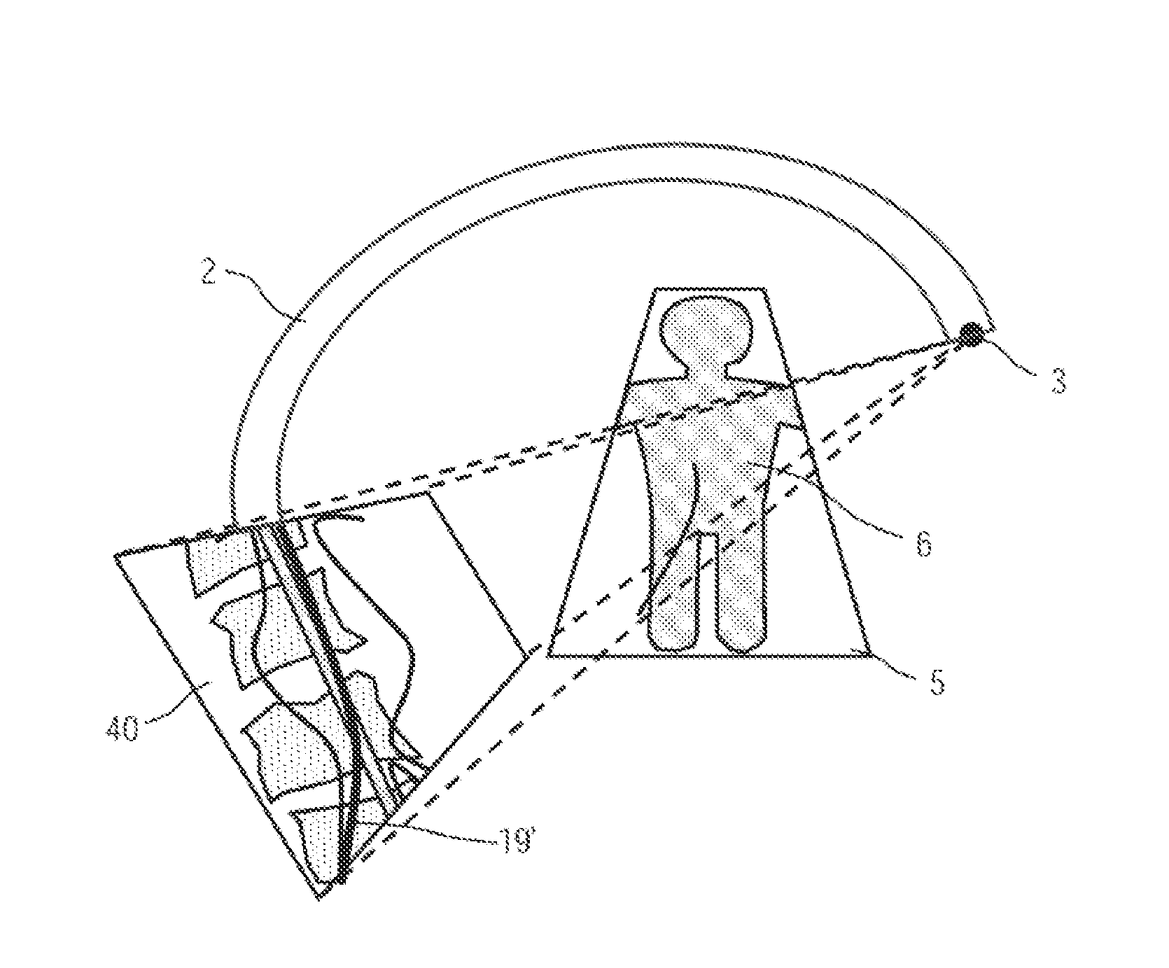
[0058]Based on FIGS. 5 and 6, the principle of a 2D / 3D and a 2D / 2D overlay are explained in ...


PUM


Abstract

An angiographic examination method for depicting a target region as an examination object using an angiography system includes capturing a volume data set of the target region with the examination object, registering the volume data set to a C-arm, and extracting information about an assumed course of the examination object in the volume data set. The method also includes generating a 2D projection image of a medical instrument in the target region, 2D/3D merging the 2D projection image and the registered volume data set for generating a 2D overlay image, and detecting the instrument in the 2D overlay image with a first projection matrix. The method includes generating a virtual 2D projection using a virtual projection matrix, 3D reconstructing the instrument, and distorting at least part of the reference image such that the current and the assumed course of vessels are made to be congruent.

Description

[0001]This application claims the benefit of DE 10 2013 219 737.3, filed on Sep. 30, 2013, which is hereby incorporated by reference in its entirety.BACKGROUND[0002]The present embodiments relate to an angiographic examination method for depicting a target region inside a patient with a vascular system as an examination object.[0003]An angiography system for the performance of an angiographic examination method is known, for example, from U.S. Pat. No. 7,500,784 B2, which is explained below based on FIG. 1.[0004]FIG. 1 shows a monoplanar X-ray system depicted as an example with a C-arm 2 held by a stand 1 in the form of a six-axis industrial or articulated robot. The X-ray system includes an X-ray source (e.g., an X-ray emitter 3 with X-ray tube and collimator) and an X-ray image detector 4 being attached to ends of the C-arm 2 as an image recording unit.[0005]Using the articulated robot known, for example, from U.S. Pat. No. 7,500,784 B2, which may have six axes of rotation and thu...

Claims


Application Information

Patent Timeline
Patent Type & Authority Applications(United States)
IPC IPC(8): A61B6/12A61B6/00
CPCA61B6/12A61B6/504A61B6/463A61B6/5235A61B6/4441A61B6/03A61B6/4458A61B6/481A61B6/487A61B6/5223G06T2207/10081G06T2207/30101G06T7/30
Inventor PFISTER, MARCUS
Owner SIEMENS HEALTHCARE GMBH
Why Eureka
Try Eureka