
Aluminum alloy for die-casting, metal case for portable electrical device and method of manufacturing the metal case

a technology of aluminum alloy and die-casting, which is applied in the direction of metal casings, printing, surface reaction electrolytic coatings, etc., can solve the problems of low hardness of plastic bodies, easy generation of surface defects such as scratches, and easy damage of plastic bodies, etc., to achieve the effect of improving die-casting ability, reducing surface defects, and reducing production costs

Inactive Publication Date: 2015-04-09
GK
View PDF5 Cites 10 Cited by
  • Summary
  • Abstract
  • Description
  • Claims
  • Application Information

AI Technical Summary

Benefits of technology

The patent describes an aluminum alloy that can be used to make a case for a portable electrical device. This alloy has good strength, gloss, and color for an external case while not using silicon, which is commonly used in other alloys. The alloy has high reflectivity and glossiness, and can be cast using a die-casting process. The finished case has no visible defects, is durable, and has good appearance and performance characteristics. The alloy also has superior anodizability, meaning it can be easily coated with a protective layer. The alloy is made up of about 94% aluminum, with a temperature of the molten alloy ranging from 700°C to 790°C. Overall, this alloy can create a case for a portable electrical device that is strong, glossy, and has good coloring and appearance.

Problems solved by technology

However, a plastic body has a low surface hardness.
Thus, a surface defect such as a scratch may be easily generated.
Furthermore, the plastic body is may be easily damaged by impact.
Furthermore, reducing a thickness of the plastic body is limited so that the plastic body may have a desired structural strength.
However, coloring a metal is difficult and limited so that a product from a metal hardly achieves various colors.
However, making a complicated shape such as rib, boss or the like, which is required for an electrical device, is difficult.
Thus, processing a following anodizing process may be difficult, or uniform coloring may be difficult due to surface reduction.

Method used


Image

  • Aluminum alloy for die-casting, metal case for portable electrical device and method of manufacturing the metal case
  • Aluminum alloy for die-casting, metal case for portable electrical device and method of manufacturing the metal case
  • Aluminum alloy for die-casting, metal case for portable electrical device and method of manufacturing the metal case

Examples


Embodiment Construction

[0048]The present inventive concept now will be described more fully hereinafter with reference to the accompanying drawings, in which exemplary embodiments of the present invention are shown. The present inventive concept may, however, be embodied in many different forms and should not be construed as limited to the exemplary embodiments set fourth herein.

[0049]Rather, these exemplary embodiments are provided so that this disclosure will be thorough and complete, and will fully convey the scope of the present invention to those skilled in the art.

[0050]It will be understood that, although the terms first, second, third, etc. may be used herein to describe various elements, components, regions, layers and / or sections, these elements, components, regions, layers and / or sections should not be limited by these terms. These terms are only used to distinguish one element, component, region, layer or section from another region, layer or section. Thus, a first element, component, region, ...


PUM

PropertyMeasurementUnit
temperatureaaaaaaaaaa

Abstract

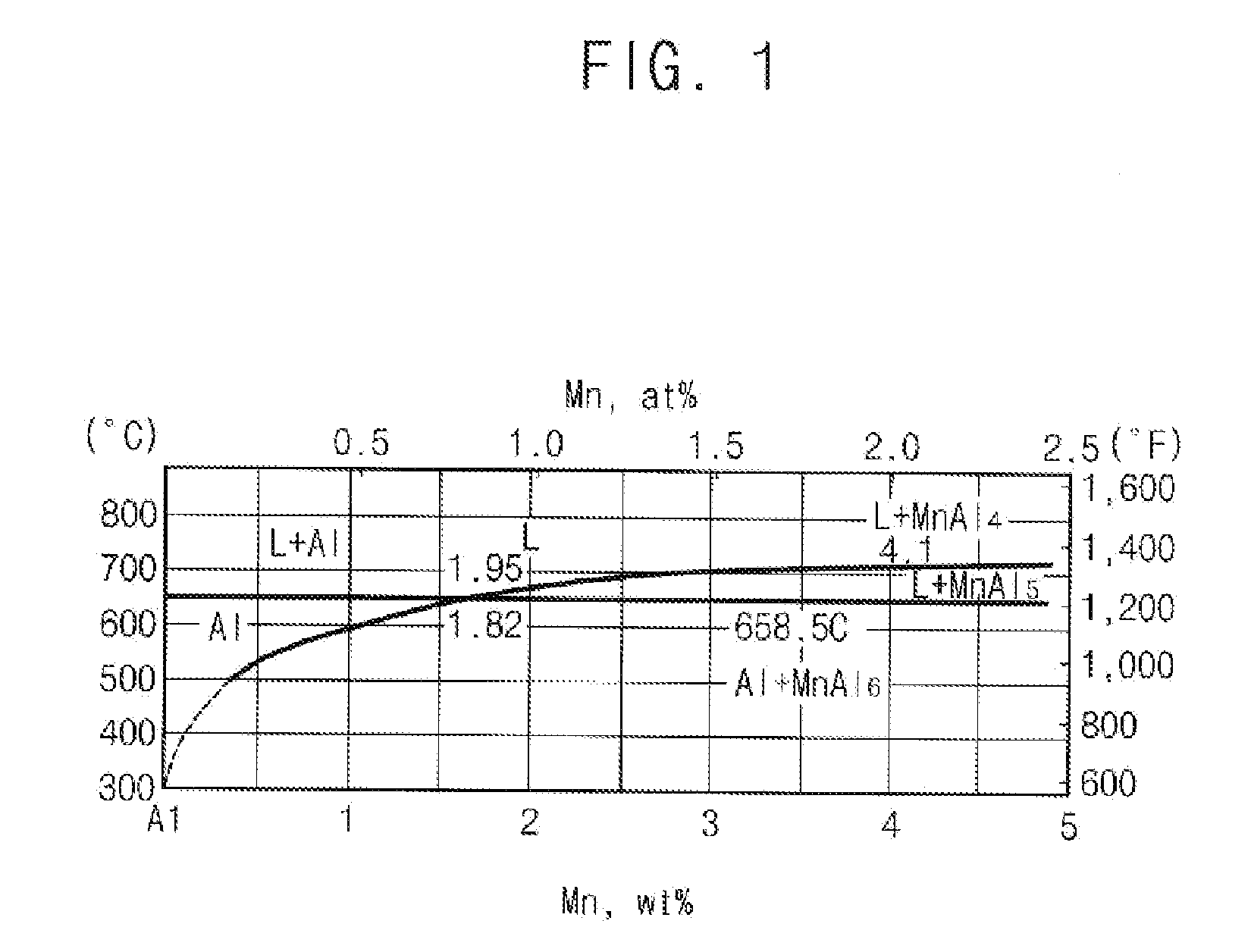
An aluminum alloy for die-casting, a metal case for a portable electrical device, and a method of manufacturing the metal case are disclosed. The aluminum alloy for die-casting includes about 1.95% to about 4.10% by weight of manganese, about 0.1% to about 2.0% by weight of zinc, about 0.3% to about 0.8% by weight of zircon, about 0.03% to about 0.09% by weight of titanium, and a remainder of aluminum. Thus, the aluminum alloy may provide a mechanical property and a glossiness that are appropriate for a case of a portable electrical device.

Description

CROSS REFERENCE TO RELATED APPLICATION[0001]This application claims priority from and the benefit of Korean Patent Application No. 10-2013-0119389, filed on Oct. 7, 2013, which is hereby incorporated by reference for all purposes as if fully set forth herein.BACKGROUND[0002]1. Field[0003]Example embodiments relate to an aluminum alloy for die-casting, a metal case for a portable electrical device, and a method of manufacturing the metal case. More particularly, example embodiments relate to an aluminum alloy for die-casting, which can achieve uniform coloring and high glossiness through a following color-anodizing process to improve fanciness of a portable electrical device, a metal case for a portable electrical device, and a method of manufacturing the metal case.[0004]2. Discussion of the Background[0005]Recently, competition between product makers for reducing size and thickness of a product is intense as portability and high-functionality is required in the field of a portable ...

Claims


Application Information

Patent Timeline
Patent Type & Authority Applications(United States)
IPC IPC(8): H05K5/04B22D17/20C25D11/24C22C21/00
CPCH05K5/04C22C21/00C25D11/243C25D11/246B22D17/2015C22C21/10B22D17/2218B22D21/007C22F1/04C25D11/04G06F1/1656G06F1/181B22D21/04
Inventor JEONG, JONG HOONSHIN, DONG SUNG
Owner GK
Learn More