Electrical apparatus and control system
a control system and electric power technology, applied in the direction of motor/generator/converter stopper, dynamo-electric converter control, wellbore/well accessories, etc., can solve the problems of periodic reversal of the direction of energy flow, system and method are susceptible to modification, heats wires, etc., to reduce the overall current, economical, efficient and flexible operation
- Summary
- Abstract
- Description
- Claims
- Application Information
AI Technical Summary
Benefits of technology
Problems solved by technology
Method used
Image
Examples
example # 0
Analysis of Example #0
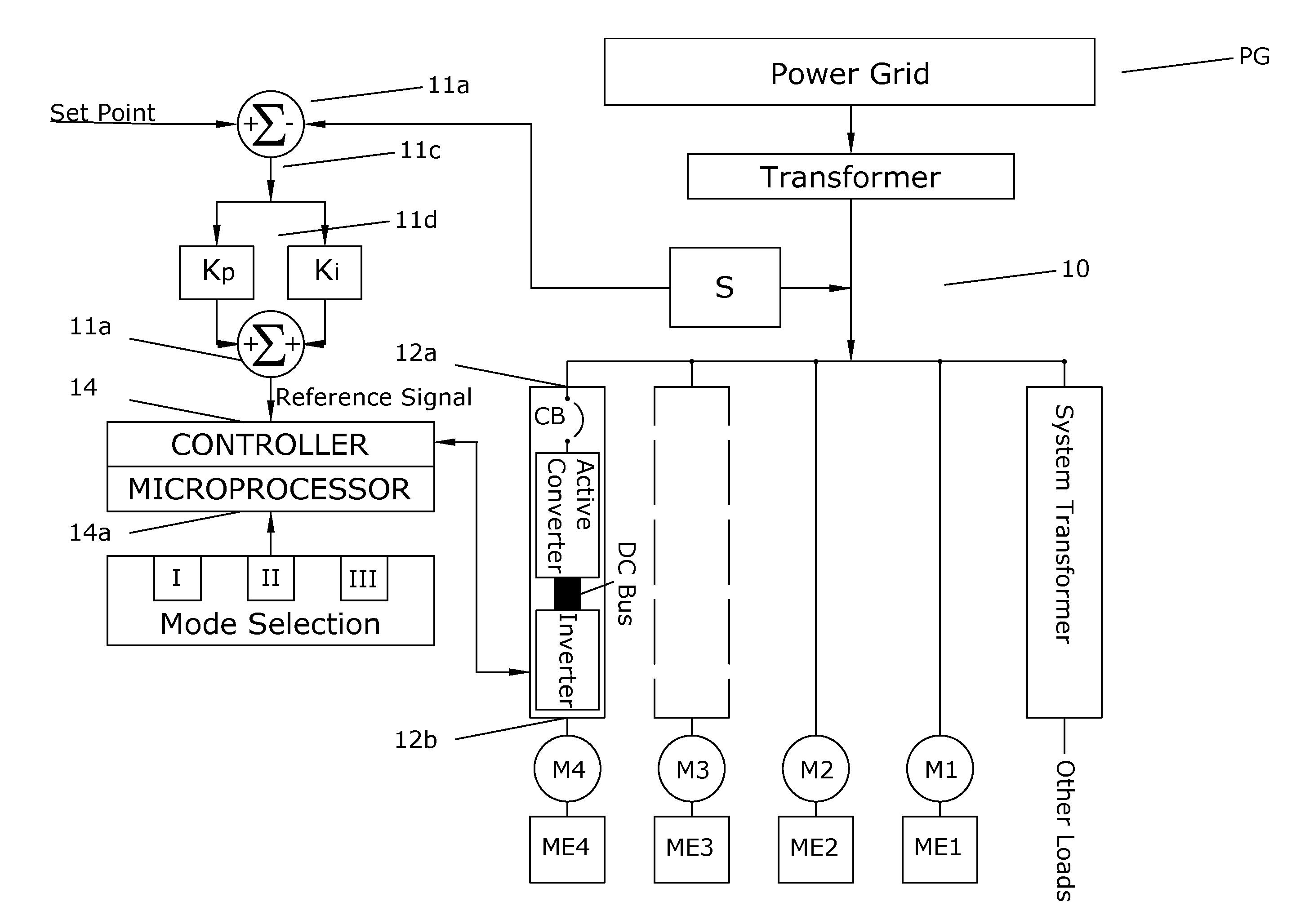
[0248]Voltage at CKT-PRIMARY is 12,362 VAC. This voltage level is 108 VAC lower than the nominal voltage at this circuit location, which is 12,470. 108 VAC represents a 0.9% voltage drop vs. nominal voltage. This small voltage drop is due to the impedance of the T-PAD5A transformer. Transformers, in general, will have a slight voltage drop as which increases as the current through the transformer increases. At maximum current, 116 Amps for T-PAD5A, the voltage drop at CKT-PRIMARY would be 5.75% of nominal voltage. The number 5.75% is the rated impedance of the transformer shown on the drawing in FIG. 1.
[0249]Current at CKT-PRIMARY is 17 Amps. This current is due, in its entirety, to the magnetizing of the smaller distribution transformers in the electrical power distribution system.
[0250]KW at CKT-PRIMARY is 0. This example is considered at no load with ideal conductors and ideal transformers. Therefore, there is no real power transferred in this example.
[0251]...
example # 1
Analysis of Example #1
[0255]Focusing on CKT-W component 334W is useful. Consider the reactive power shown component 334W in Example #1 vs. CKT-W component 334W in Example #0. In both examples, the required reactive power is 40 KVAR. As we established in Example #0, the 40 KVAR for this component is the required reactive current to magnetize the distribution transformer associated with this particular component. The reason no additional reactive power is indicated in Example #1 is that this component is equipped with an Variable frequency AC drive with Active Converter. The Variable frequency AC drive with Active Converter requires zero magnetizing current to operate the motor in all circumstances. As will be discussed in subsequent examples, the Variable frequency AC drive with Active Converter has the capability to inject or consume reactive power according to a reference and a control mode to be described later. The power factor shown for CKT-W component 334W is shown to be 0.98. ...
example # 2
Analysis of Example #2
[0260]There is little change between Example #2 and Example #1. However, Example #2 represents a much more realistic operating configuration for most electrical power distribution networks. It is very common, in practice, to measure loading levels of between 40% and 70% on most electrical power distribution networks. In fact, most power distribution networks operate at this level of load 99% of to the time. Looking into specifics characteristics of Example #2, the overall power factor measured at CKT-PRIMARY is 0.78. The transformer loading is 1479 KVAR or 59% of rated load. Both the power factor and loading level of Example #2 are significantly lower than that in Example #1. Again, Example #2 is a more realistic representative configuration of most real-world electrical power distribution networks.
Example #3
All Equipment Operating at 50% Load
[0261]Transformers energized. Reactive current required to magnetize distribution transformers and induction motors. Max...
PUM
 Abstract
Description
Claims
Application Information
 - R&D
- Intellectual Property
- Life Sciences
- Materials
- Tech Scout
- Unparalleled Data Quality
- Higher Quality Content
- 60% Fewer Hallucinations
Browse by: Latest US Patents, China's latest patents, Technical Efficacy Thesaurus, Application Domain, Technology Topic, Popular Technical Reports.
© 2025 PatSnap. All rights reserved.Legal|Privacy policy|Modern Slavery Act Transparency Statement|Sitemap|About US| Contact US: help@patsnap.com


