Methods for Depositing Silicon Nitride Films

a technology of silicon nitride and film, which is applied in the direction of superimposed coating process, organic chemistry, vacuum evaporation coating, etc., can solve problems such as handling and usag

Active Publication Date: 2015-04-09
VERSUM MATERIALS US LLC
View PDF11 Cites 214 Cited by
  • Summary
  • Abstract
  • Description
  • Claims
  • Application Information

AI Technical Summary

Problems solved by technology

However, there are several drawbacks using this method.
This may present problems in handling and usage.

Method used


Image

  • Methods for Depositing Silicon Nitride Films
  • Methods for Depositing Silicon Nitride Films
  • Methods for Depositing Silicon Nitride Films

Examples


example 1

PEALD Silicon Nitride Film Using Di-Iso-Propylaminosilane (DIPAS) and Ar / N2 Plasma

[0122]The silicon wafer was loaded into Stellar 3000 PEALD reactor and heated to 300° C. with chamber pressure of about 2 Torr. The deposition process was performed using the steps described in Table 2 and repeated 1000 times. Process conditions used was the same as described in Comparative Example 1, with varying precursor pulse: 0.5 to 5 seconds. The deposition rates and refractive index are summarized in Table 3 below.

TABLE 3Deposition rate and refractive index of deposited films for silicon nitridecontaining films using DIPAS and Ar / N2 plasmaDeposition RateSample No.DIPAS pulse (s)(Å / cycle)Refractive index10.50.181.97210.201.96310.201.95420.241.95550.301.94650.251.95

TABLE 4Properties of silicon nitride film using DIPAS and Ar / N2 plasmaCO contentDensityWER in dHFSample No.(%)(%)(g / cc)(Å / sec)25.62.82.80.455.21.52.70.366.22.12.70.4

[0123]Films 2, 5 and 6 were picked to represent the examples for furthe...

example 2

PEALD Silicon Nitride Containing Film Using Di-Sec-Butylaminosilane (DSBAS) and Ar / N2 Plasma

[0124]The deposition process was performed using the steps described in Table 2 and repeated 1000 times. The process conditions used were the same as described in Comparative Example 1, with a varying precursor pulse ranging from 0.2 to 5 seconds. The deposition rate and refractive index for all deposited films were measured and are provided below in Table 5. Both deposition rate and refractive index shows are consistent with DIPAS as shown in Example 1.

TABLE 5Deposition rate and refractive index of deposited films for silicon nitridecontaining films using DSBAS and Ar / N2 plasmaDeposition RateSample No.DSBAS pulse (s)(Å / cycle)Refractive index10.20.161.9620.50.191.93310.221.92450.301.90

example 3

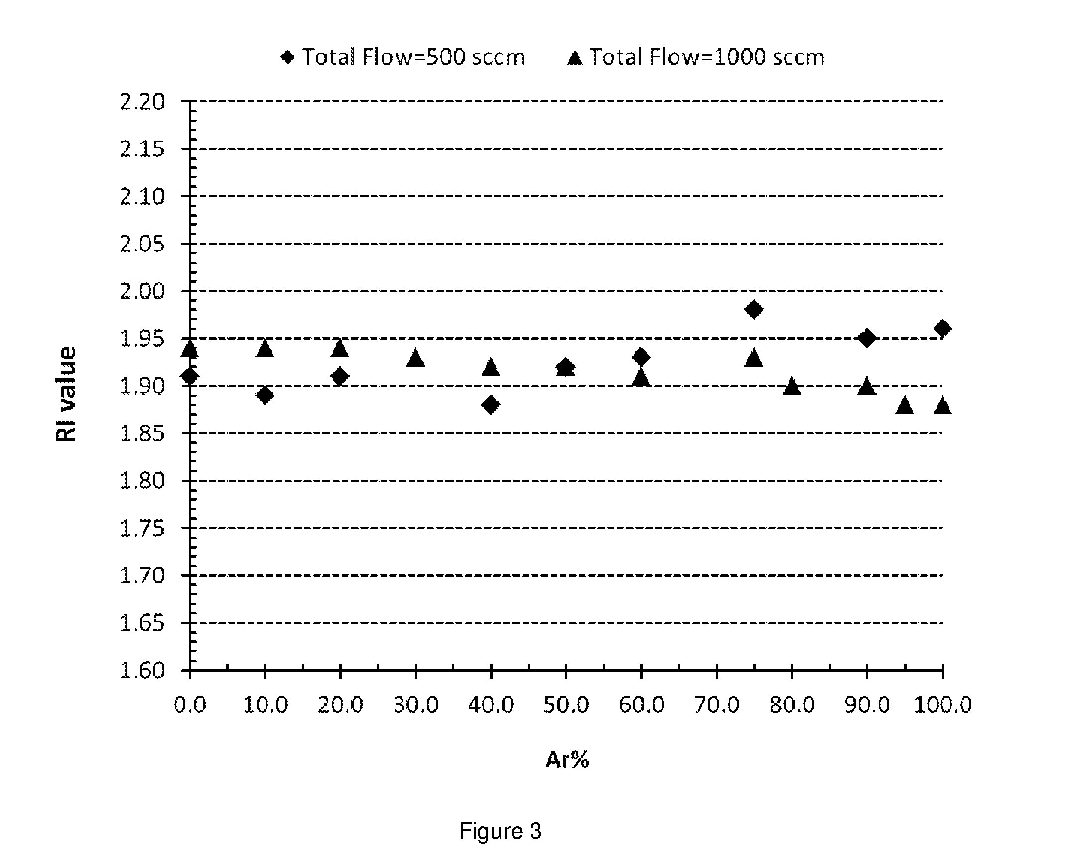
PEALD Silicon Nitride Containing Film Using Di-Sec-Butylaminosilane (DSBAS) and Ar / N2 Plasma with Various Percentages of Argon (Ar)

[0125]The silicon wafer was loaded into Stellar 3000 PEALD reactor and heated to 300° C. with chamber pressure of about 2 Torr. DSBAS was delivered to the chamber at 1 Torr vapor pressure using 200 sccm Ar carrier gas at room temperature. Substrate temperature was set to 300° C. Gas and precursor lines temperature were adjusted accordingly to prevent condensation prior to the reactor. The deposition was conducted using the steps described in Table 2 and using the following process parameters:

[0126]1. Introduce an organoaminosilane precursor to the reactor: DSBAS[0127]Argon flow=300 sccm[0128]Si precursor pulse: 1 second

[0129]2. Inert gas purge[0130]Argon flow: 300 sccm[0131]Purge time: 5 seconds

[0132]3. Plasma on[0133]Argon flow: 325 to 425 sccm[0134]Nitrogen flow: 75 to 200 sccm[0135]Total flow of Ar and nitrogen: 500 sccm[0136]Chamber pressure: 2 Torr[...


PUM

PropertyMeasurementUnit
densityaaaaaaaaaa
temperaturesaaaaaaaaaa

Abstract

Described herein are methods for forming silicon nitride films. In one aspect, there is provided a method of forming a silicon nitride film comprising the steps of: providing a substrate in a reactor; introducing into the reactor an at least one organoaminosilane having a least one SiH3 group described herein wherein the at least one organoaminosilane reacts on at least a portion of the surface of the substrate to provide a chemisorbed layer; purging the reactor with a purge gas; introducing a plasma comprising nitrogen and an inert gas into the reactor to react with at least a portion of the chemisorbed layer and provide at least one reactive site wherein the plasma is generated at a power density ranging from about 0.01 to about 1.5 W / cm2.

Description

CROSS REFERENCE TO RELATED APPLICATIONS[0001]This application claims the benefit of U.S. Provisional Application No. 61 / 886,406, filed Oct. 3, 2013, which is hereby incorporated by reference as if fully set forth.BACKGROUND OF THE INVENTION[0002]Described herein is a method for depositing conformal, stoichiometric or non-stoichiometric, silicon nitride film using one or more organoaminosilane precursors. More specifically, described herein are plasma-based processes including, but not limited to, plasma enhanced atomic layer deposition (“PEALD”), plasma enhanced cyclic chemical vapor deposition (“PECCVD”) that are used for depositing silicon nitride films that are in the fabrication of integrated circuit devices.[0003]Low pressure chemical vapor deposition (LPCVD) processes are one of the more widely accepted methods used by semiconductor industry for the deposition of silicon nitride films. Low pressure chemical vapor deposition (LPCVD) using ammonia may require deposition temperat...

Claims


Application Information

Patent Timeline
Patent Type & Authority Applications(United States)
IPC IPC(8): H01L21/02
CPCH01L21/0217H01L21/02211H01L21/0228H01L21/02274H01L21/02222C07F7/10C23C16/18C23C16/345C23C16/45523C23C16/45542C23C16/45553C23C14/027C23C14/548C23C28/42
Inventor HARIPIN, CHANDRAMALLIKARJUNAN, ANUPAMALEI, XINJIANKIM, MOO-SUNGCUTHILL, KIRK SCOTTO'NEILL, MARK LEONARD
Owner VERSUM MATERIALS US LLC
Why Eureka
Try Eureka