Method for compensating a signal from a pressure measurement device within an internal combustion engine

Inactive Publication Date: 2015-04-09
CONTINENTAL AUTOMOTIVE FRANCE +1
View PDF4 Cites 2 Cited by
  • Summary
  • Abstract
  • Description
  • Claims
  • Application Information

AI Technical Summary

Benefits of technology

The invention allows for reliable and accurate compensation of sensor output voltage signals during plateau and peak phases. This is achieved by using a linear regression analysis of previous slope and intercept values during a plateau phase to approximate the values during the peak phase. The analysis is based on stored coefficients and the output voltage signal of the sensor. The technical effect is the improved accuracy and precision of sensor output voltage signals during the plateau and peak phases.

Problems solved by technology

However, this voltage signal is subjected to noise and drift due, inter alia, to the phenomena of pyroelectricity and / or vibrations to which said pressure measurement sensor is subjected.
However, the disadvantages of a signal processing method of this type are as follows:since each point of the signal is processed by a complex calculation using a Kalman filter, a signal processing method of this type is unwieldy and uses a substantial amount of the ASIC circuit memory,this method is difficult to calibrate, since it comprises four variables to be parameterized: one slope and constant gain for the fast Kalman filter and a different slope gain and a different constant gain for the slow Kalman filter,at an engine speed below 1000 rpm, the processed signal resulting from this processing method is significantly deformed and therefore difficult to use.

Method used


Image

  • Method for compensating a signal from a pressure measurement device within an internal combustion engine
  • Method for compensating a signal from a pressure measurement device within an internal combustion engine
  • Method for compensating a signal from a pressure measurement device within an internal combustion engine

Examples


Embodiment Construction

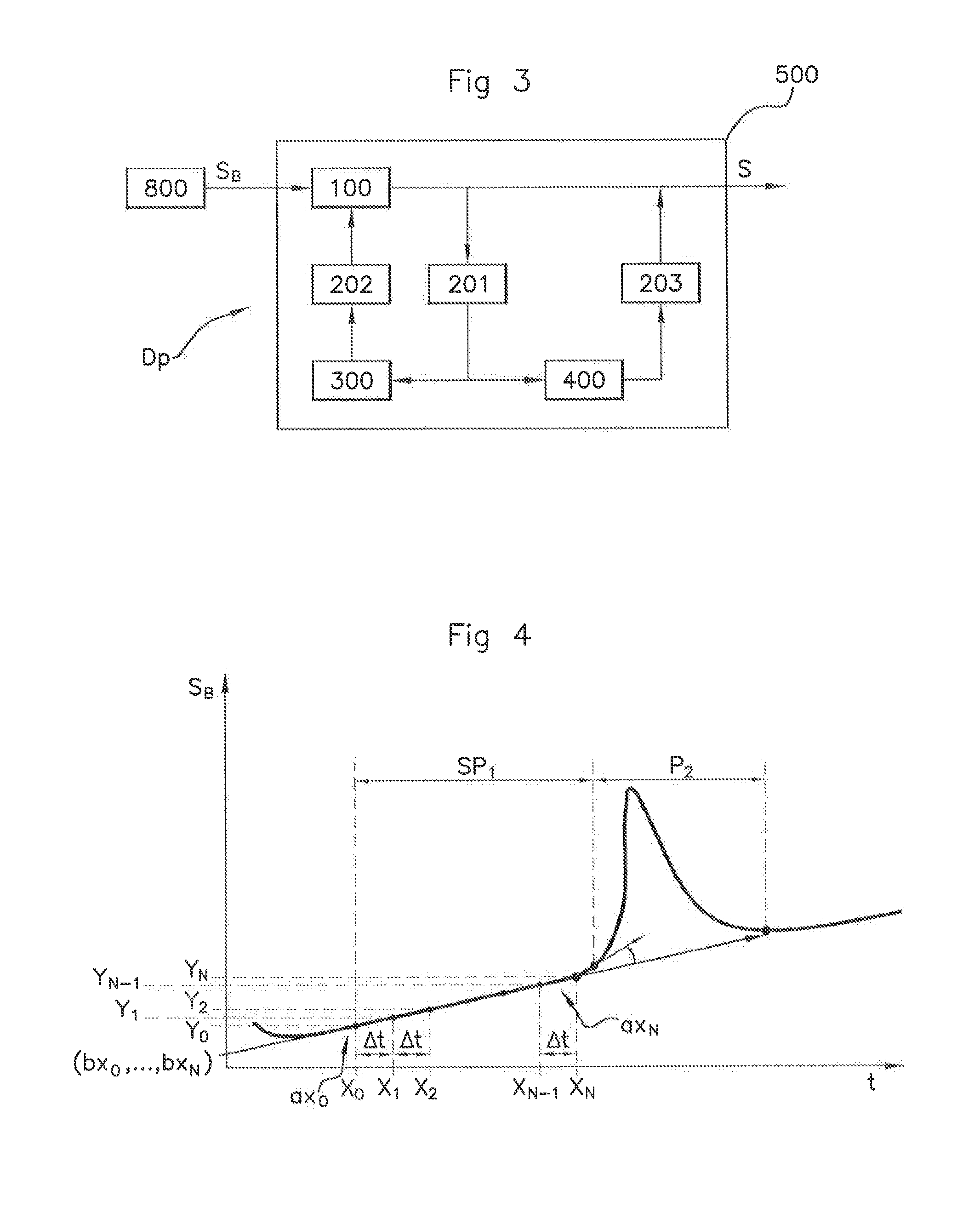
[0059]FIG. 3 shows an embodiment of the pressure measurement device DP according to the invention. Such a measurement device DP includes a pressure measurement sensor 800 connected to a processing unit 500.

[0060]Still with reference to FIG. 3, the output signal SB of the pressure measurement sensor 800 is acquired and processed by the processing unit 500, for example built into an integrated circuit (ASIC, not shown in FIG. 3) in order to deliver a processed output signal S.

[0061]In this example, the processing unit 500 includes a charge amplifier 100, a first analog / digital converter 201, a second digital / analog converter 202, a third digital / analog converter 203, filtering means 300 and signal processing means 400.

[0062]The first analog / digital converter 201 is connected, on the one hand, to the charge amplifier 100 and, on the other hand, to the filtering means 302 and to the signal processing means 400.

[0063]The filtering means 300 filter the noise present on the signal SB and a...


PUM


Abstract

A method for processing a signal (SB) from a pressure measurement device (DP) in a combustion chamber of a cylinder of an internal combustion engine includes: detecting the start of a plateau phase (SP1); calculating a pair of values of a slope (ax0, . . . , axN) and an intercept (bx0, . . . , bxN) of a straight line approximating the values of the signal acquired by the processing unit during the plateau phase; determining a voltage compensation value of the signal on the basis of each pair of calculated slope and intercept values; compensating the output signal (SB) of the pressure sensor on the basis of the determined voltage compensation value; detecting the start of a voltage peak phase (P2) following the plateau phase (SP1); and, during the detected peak phase, compensating the signal (SB) on the basis of the last pair of slope (axN) and intercept (bxN) values calculated during the plateau phase.

Description

FIELD OF THE INVENTION[0001]The present invention relates to the field of pressure measurement in a cylinder of an internal combustion engine and concerns more particularly a device and a method for compensating the drift of an output signal of a pressure measurement sensor.BACKGROUND OF THE INVENTION[0002]An internal combustion engine conventionally comprises cylinders in which pistons slide, each defining a combustion chamber in which fuel and an oxidizer are introduced in order to carry out the combustion of the mixture. The engine transforms the energy released by this combustion into mechanical energy.[0003]It is known to equip an internal combustion engine with a device to measure the pressure prevailing within the combustion chambers of the cylinders including pressure measurement sensors and associated electronics.[0004]The value of this pressure enables an electronic computing system (or ECU: “Engine Control Unit”), installed on-board a motor vehicle equipped with an intern...

Claims


Application Information

Patent Timeline
IPC IPC(8): G01M15/08G01L7/00
CPCG01L7/00G01M15/08F02D41/28F02D35/023F02D2041/1429F02D2041/1432F02D2041/286
Inventor DUCHEMIN, CHRISTOPHE
Owner CONTINENTAL AUTOMOTIVE FRANCE
Why Eureka
Try Eureka