Excavated underground caverns for fluid storage

a cavern and underground technology, applied in the direction of transportation and packaging, mechanical equipment, machines/engines, etc., can solve the problems of limited use of depleted hydrocarbon bearing zones, limited use of depleted hydrocarbon formations, and limited use of depleted hydrocarbon reservoirs, so as to minimize the surface area of land associated, the effect of maximizing storage volumes and constant injection and discharge pressur

Inactive Publication Date: 2015-05-07
GENERAL COMPRESSION
View PDF6 Cites 14 Cited by
  • Summary
  • Abstract
  • Description
  • Claims
  • Application Information

AI Technical Summary

Benefits of technology

[0008]The present application describes underground storage caverns that may be formed by mechanical excavation of a subsurface formation in a controlled fashion. In some embodiments, the present application provides storage caverns formed by employing tunnel boring techniques, which may be substantially horizontal or slightly inclined. The caverns may be formed in a controlled fashion, are scalable, and may employ geometries to maximize storage volumes while minimizing the surface area of land associated with the storage facility. In addition, the caverns may be formed in a wide array of geologic formations and they may be located essentially anywhere a suitable geologic formation is located regardless of, for example, population density. Storage caverns as described herein may further employ hydraulic pressure compensation to manage wide pressure variations in the storage caverns, and to provide relatively constant injection and discharge pressures when introducing or releasing stored fluids. In some embodiments, the caverns may be employed in a compressed air energy storage (CAES) system for storing energy in the form of compressed air. Alternatively, the present caverns may be employed for the storage of natural gas and hydrocarbon liquids. These embodiments are described herein.

Problems solved by technology

However, the use of depleted hydrocarbon reservoirs may be limited for some storage applications.
For example, the use of depleted hydrocarbon bearing zones is limited by the location of such formations, which may be in remote areas and distant from sites where storage is desired.
Furthermore, the use of depleted hydrocarbon formations may be limited by the dynamic characteristics of the formation.
Accordingly, such applications may not be compatible with formations wherein the permeability and porosity characteristics of the formation do not permit sufficient injection and / or withdrawal rates.
Thus, suitably located depleted hydrocarbon formations, having appropriate permeability, porosity, and flow characteristics may be unavailable for a given storage application.
Solution mining of salt beds and domes may be a time consuming process, and typically produces large quantities of brine which must be treated and / or disposed of.
In addition, the use of salt caverns for fluid storage, like depleted hydrocarbon formations, is limited by the geographical location of salt formations, which may not be convenient or appropriate for a desired fluid storage need or application.
However, blasting employed in the formation of such structures typically produces fractures of the surrounding rock formations, and may also weaken the surrounding rock.
Accordingly, the fractures may result in structures which are not suitable to contain stored fluids under pressure.
Such losses are generally unacceptable, particularly in fluid storage applications where pressurized fluids are retained (e.g., compressed gas storage).
Furthermore, blasting may damage the integrity of the overburden rock, requiring extensive bracing and / or shoring to keep the resultant cavern open.
In addition, blasting may produce large, irregular debris which may require grinding or other size reduction prior to removal.
Further, blasting to form caverns may not be suitable for certain locations (e.g., densely populated areas), and thus the location of blasted caverns may be limited.

Method used


Image

  • Excavated underground caverns for fluid storage
  • Excavated underground caverns for fluid storage
  • Excavated underground caverns for fluid storage

Examples


Embodiment Construction

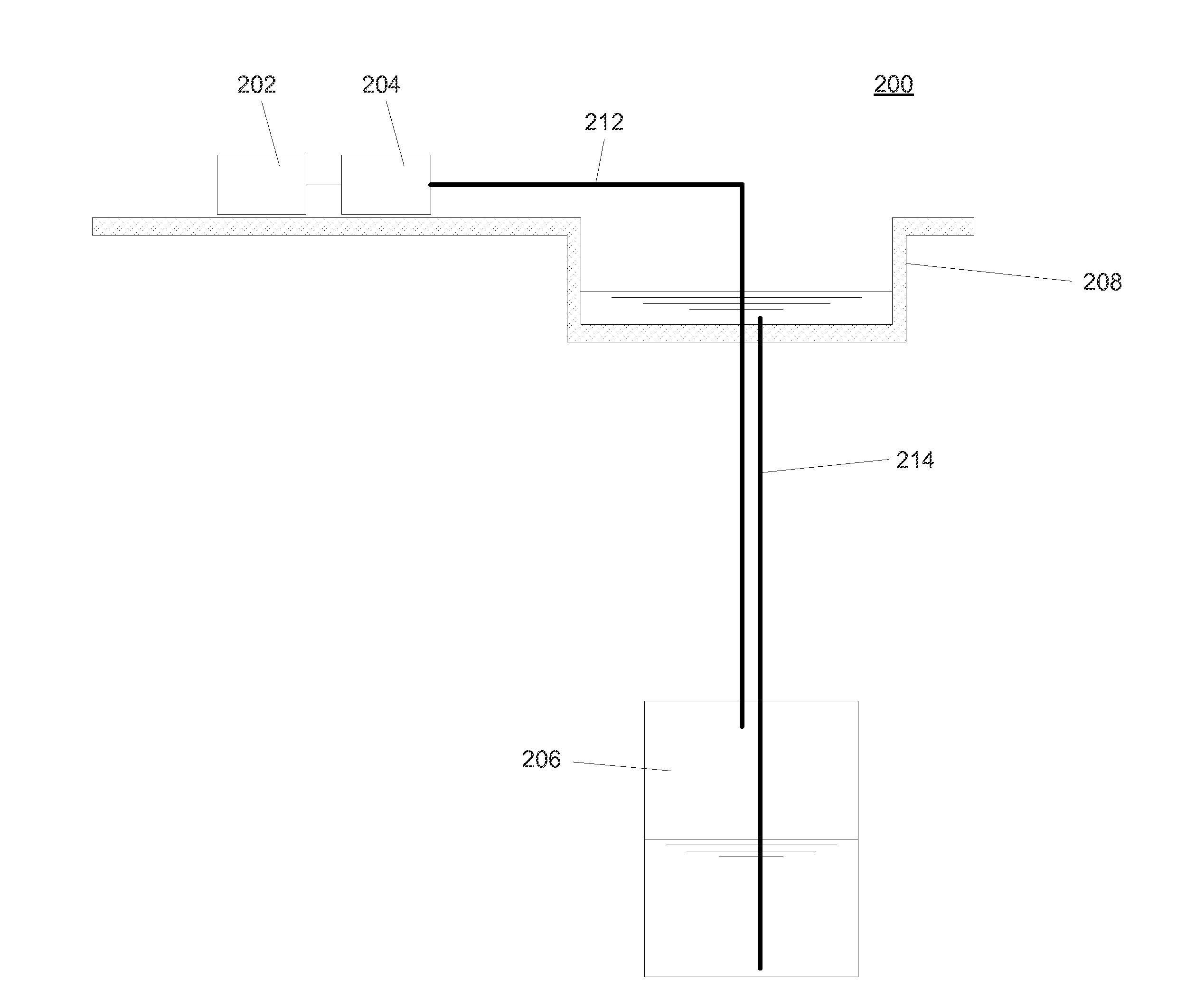
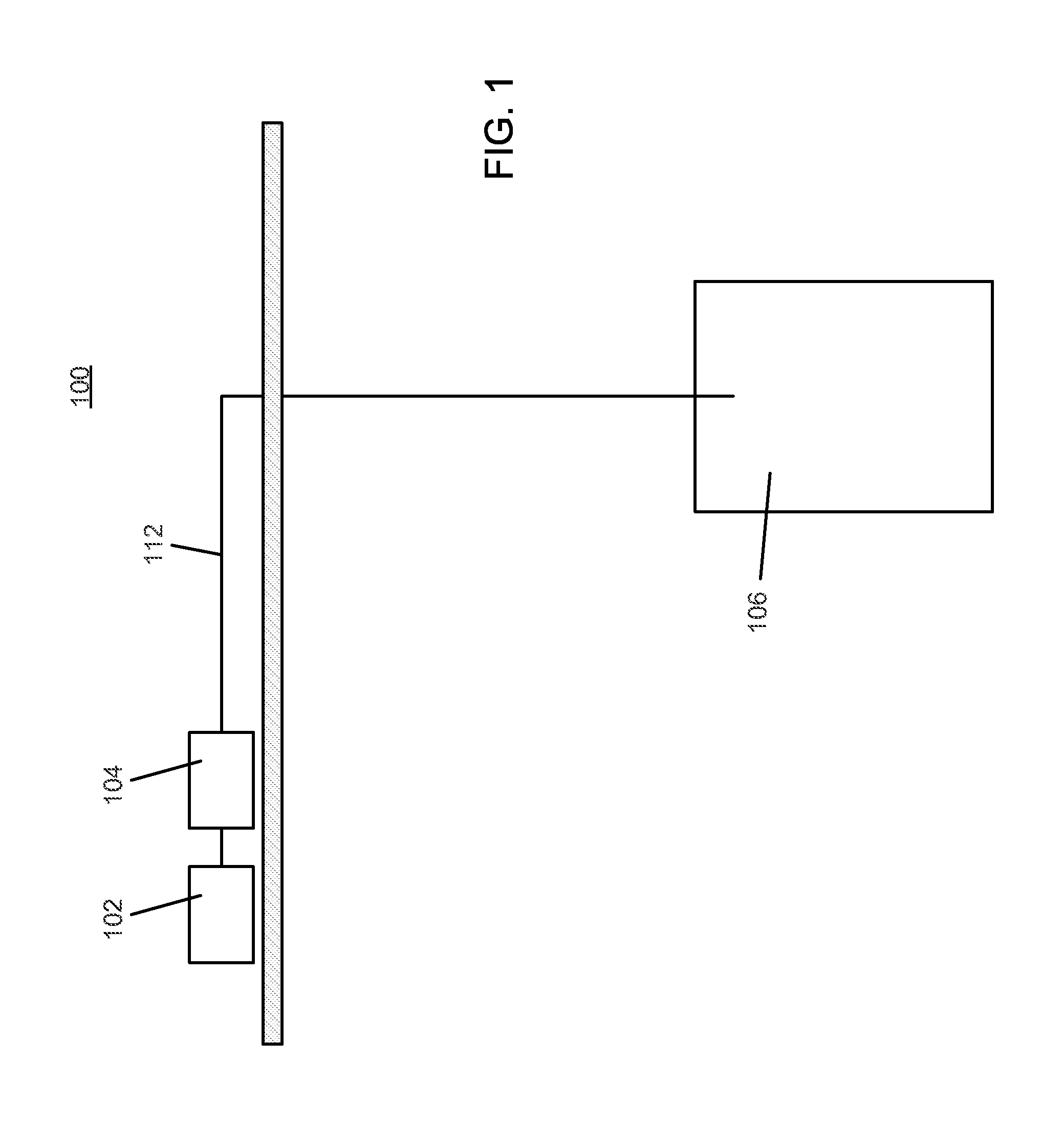
[0033]Systems and methods for the storage of a compressed gas (such as air, natural gas, hydrogen (H2), helium (He) or argon (Ar)), or a liquid, in underground storage caverns are described herein. The underground storage caverns can be used, for example, to store hydrocarbons such as natural gas, natural gas liquids (NGL) or liquefied petroleum gases (LPG) for later recovery and use. The underground storage caverns can also be used, for example, to store energy in the form of compressed gas, such as air, in a compressed air energy storage (CAES) system. The caverns can have efficient / optimal operating ranges that can vary as a function of, for example, flow rate and pressure, among other parameters. Systems and methods of operating the storage caverns are provided to allow them to function at optimal performance throughout the energy storage cycle of the compressed gas energy storage system.

[0034]Throughout the present specification, the words “a” or “an” are understood to mean “on...


PUM


Abstract

An underground fluid storage structures formed by mechanical excavation of a subsurface formation in a controlled fashion. The structure comprises vertical holes (260, 270) and transversal caverns (256) of circular section and preferably in spiral arrangement. Storage caverns as described herein may further employ hydraulic pressure compensation to prevent wide pressure variations in the storage caverns, and to provide relatively constant injection and discharge pressures when introducing or releasing stored fluids. The preferred application is compressed air energy storage (CAES) systems for storing energy in the form of compressed air in order to generate electricity.

Description

CROSS-REFERENCE TO RELATED APPLICATION[0001]This application claims priority to and the benefit of U.S. Provisional Patent Application No. 61 / 648,972, filed May 18, 2012, and entitled “Excavated Underground Caverns for Fluid Storage,” the entirety of which is hereby incorporated herein by reference.FIELD OF THE INVENTION[0002]The disclosed embodiments relate generally to systems and methods for storing a fluid, and particularly to systems and methods for storing compressed gas, such as air or natural gas.BACKGROUND[0003]Subsurface storage structures may be employed for the storage of fluids, e.g., natural gas, hydrocarbons liquids, air, carbon dioxide and / or other gases. Conventional subsurface storage may include depleted hydrocarbon-bearing reservoirs which exhibit suitable permeability and porosity, and which exhibit suitable pressure retention characteristics (e.g., provided by a shale cap or other geologic features) to retain the stored fluid for later retrieval. However, the u...

Claims


Application Information

Patent Timeline
Patent Type & Authority Applications(United States)
IPC IPC(8): B65G5/00F02C9/16F02C6/16
CPCB65G5/00F02C9/16F02C6/16Y02E60/16
Inventor INGERSOLL, ERIC D.CARTER, PRESTON
Owner GENERAL COMPRESSION
Why Eureka
Try Eureka