
Controlling etch rate drift and particles during plasma processing

Inactive Publication Date: 2015-05-07
TOKYO ELECTRON LTD
View PDF5 Cites 112 Cited by
  • Summary
  • Abstract
  • Description
  • Claims
  • Application Information

AI Technical Summary

Benefits of technology

The invention is a plasma processing system for processing semiconductor substrates. The system includes a plasma chamber, a radio frequency or microwave power source, and a low pressure vacuum system. The plasma chamber surface is made of a specific layer that prevents reactions between the substrate and the plasma. The method includes flowing process gases, a scavenger gas, and a reactive plasma to achieve a target yttrium hydroxide particle generation and a target etch rate of the substrate. The technical effects of this invention include improved plasma processing of semiconductor substrates with reduced damage to the substrate and higher efficiency of the plasma processing system.

Problems solved by technology

Furthermore, the surface change of the chamber wall materials / coatings may even change the RF current return or affect the plasma species like radical concentrations, plasma density, or other plasma parameters, which then cause significant process drift, (e.g. etch rate drift), or chamber matching.
However, in some processes, particles originated from Y2O3 coatings have been recognized to be a big issue especially as the lines or features become smaller and smaller.
These particles may cause device and process failure.
Also, wafer-less dry clean or wet clean are not the solution to eliminate the particle generation during the plasma process.
However, while it has successfully suppressed the particle generation, other issues appeared.
There are no clear solutions on the Y2O3 particle issue and YF3 etch rate drift issue so far due to lack of understanding of the mechanisms of the particle formation and etch rate drift.

Method used


Image

  • Controlling etch rate drift and particles during plasma processing
  • Controlling etch rate drift and particles during plasma processing
  • Controlling etch rate drift and particles during plasma processing

Examples


Embodiment Construction

[0020]In the following description, for purposes of explanation and not limitation, specific details are set forth, such as a particular geometry of a processing system, descriptions of various components and processes used therein. However, it should be understood that the invention may be practiced in other embodiments that depart from these specific details.

[0021]Similarly, for purposes of explanation, specific numbers, materials, and configurations are set forth in order to provide a thorough understanding of the invention. Nevertheless, the invention may be practiced without specific details. Furthermore, it is understood that the various embodiments shown in the figures are illustrative representations and are not necessarily drawn to scale.

[0022]Various operations will be described as multiple discrete operations in turn, in a manner that is most helpful in understanding the invention. However, the order of description should not be construed as to imply that these operations...


PUM

PropertyMeasurementUnit
Fractionaaaaaaaaaa
Fractionaaaaaaaaaa
Fractionaaaaaaaaaa

Abstract

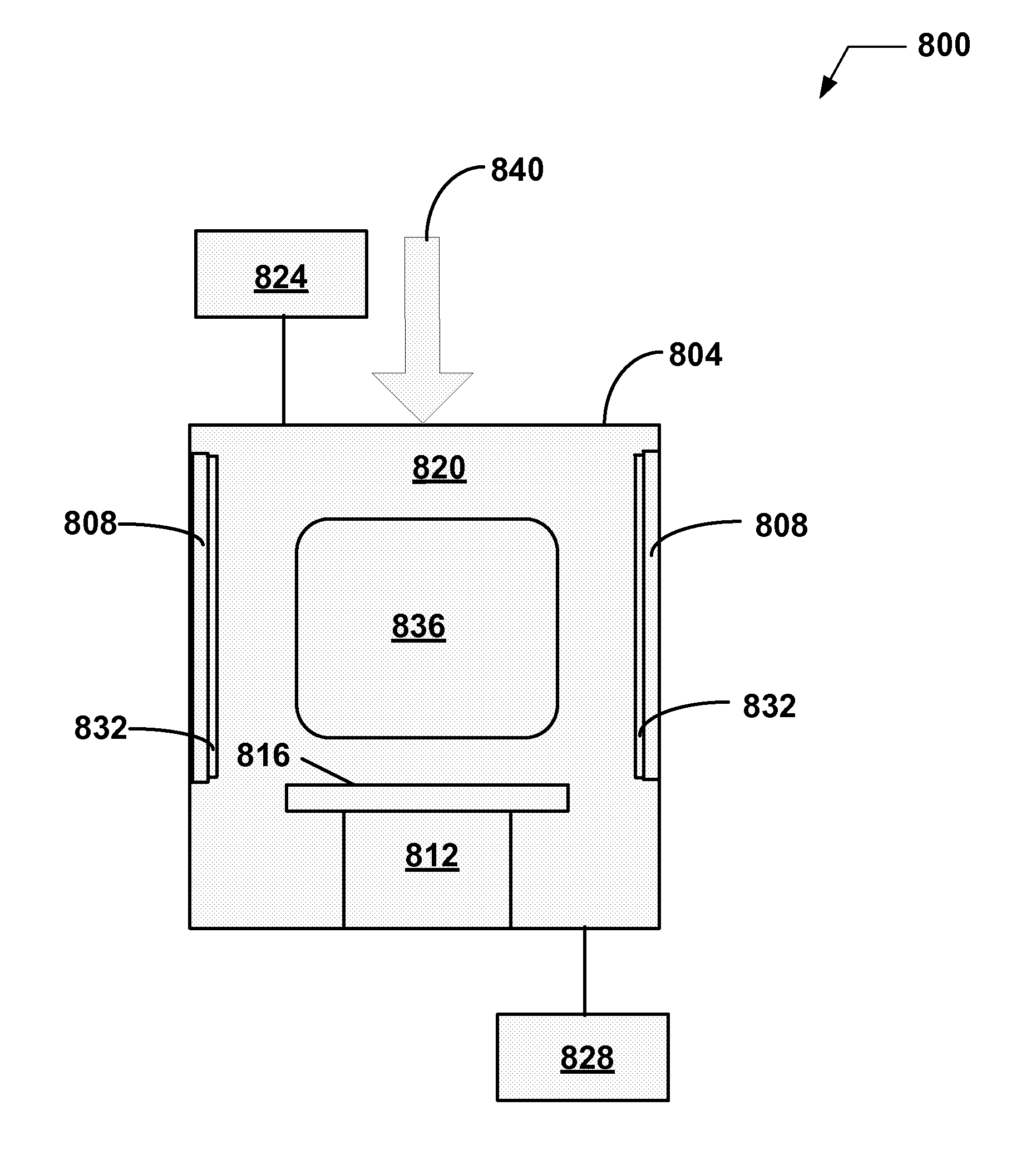
The invention is an plasma processing system with a plasma chamber for processing semiconductor substrates, comprising: a radio frequency or microwave power generator coupled to the plasma chamber; a low pressure vacuum system coupled to the plasma chamber; and at least one chamber surface that is configured to be exposed to a plasma, the chamber surface comprising: a YxOyFz layer that comprises Y in a range from 20 to 40%, O in a range from ≦60%, and F in a range of ≦75%. Alternatively, the YxOyFz layer can comprise Y in a range from 25 to 40%, O in a range from 40 to 55%, and F in a range of 5 to 35% or Y in a range from 25 to 40%, O in a range from 5 to 40%, and F in a range of 20 to 70%.

Description

CROSS REFERENCE TO RELATED APPLICATIONS[0001]The present application claims the benefit of U.S. Provisional Patent Application No. 61 / 900,112, filed on Nov. 5, 2013, entitled “Systems and Methods for Controlling Etch Rate Drift and Particles During Plasma Processing”, which is incorporated herein by reference in its entirety.BACKGROUND OF THE INVENTION[0002]1. Field of Invention[0003]This disclosure is related to methods and systems for processing a substrate and more specifically to methods and systems for controlling etch rate drift and creation of particles during plasma processing.[0004]2. Description of Related Art[0005]Chamber wall materials / coatings are critical in high density plasma process with heavily reactive and corrosive feed gas. Very often, the plasma process is very sensitive to the surface changes of chamber wall materials / coatings with time (or radio frequency (RF) time). Some chamber wall materials / coatings, (e.g. Yttrium based materials or coatings), can run ext...

Claims


Application Information

Patent Timeline
IPC IPC(8): H01L21/67H01L21/3065
CPCH01L21/3065H01L21/67069H01J37/32082C23C4/134C23C14/08H01J37/32192H01J37/32467H01J37/32477H01J37/32495H01J37/32559
Inventor ZHAO, JIANPING
Owner TOKYO ELECTRON LTD
Learn More