Rolling friction or suspension friction impact mining method and wear-resistant impact mining machine using said method

a mining method and friction technology, applied in the direction of mining structures, slitting machines, surface mining, etc., can solve the problems of shortening the service life of equipment, heavy damage to the rotating shaft, and the crushing efficiency of drilling milling or milling cutting mining methods is relatively high with extremely high energy consumption, so as to improve the resistance of mining machines and reduce the damage of the impact guiding element. , the effect of high structural strength

Inactive Publication Date: 2015-05-14
LIU SUHUA
View PDF6 Cites 7 Cited by
  • Summary
  • Abstract
  • Description
  • Claims
  • Application Information

AI Technical Summary

Benefits of technology

[0014]the guiding support etc. is provided on two or more ends of the power support to form two or more guiding support points; the two or more ends comprises spatial positions comprising two or more ends of a guiding support main body or two or more end spatial positions out of the guiding support main body; the two or more guiding support points both support the gravity of the impact head; the rubbing body, the impact guiding element and the rubbing body support etc. are matched closely to form a multi-point support impact head structure; the multi-point support impact head structure supports the impact head through multiple points to centralize an impact direction of the impact head, thus maximally increasing a centralizing width to the impact head, strengthening centralizing on the impact head, maximally controlling the impact direction of the impact head, preventing the impact drive device from being damaged by an impact damage force and a reactive force, and extending the service life of the device.
[0170]42. the impact guiding element is supported by the rubbing body to reciprocate with rolling friction or suspension friction, thus changing the original sliding friction structure, greatly reducing a running resistance of reciprocating impact of the mining machine, improving the reciprocating speed of the impact head, improving the working efficiency, greatly reducing power consumption, reducing the force load of other matched auxiliary elements, improving the service life of other auxiliary elements, and reducing related investment of the whole device; the wear-resistant efficient impact mining machine has a simple structure with high structural strength, high space utilization, reliable performance, strong manufacturability, easy processing and manufacturing, high running efficiency, energy conversation and consumption reduction, less maintenance and long service life.

Problems solved by technology

Since a relatively large rotating damage force is generated by the cutting head during drilling and milling or rolling milling and cutting, a relatively large twisting force will be generated to a rotating shaft, thus causing heavy damage to the rotating shaft and shortening the equipment service life.
The crushing efficiency of a drilling milling or milling cutting mining method is relatively high with extremely high energy consumption, and low production efficiency and lumpiness especially when tunneling crushing and ore material mining are performed at a pressure stress.
During the mining process, a large amount of dust will be further generated, which results in a poor mining environment and potential risks.
When a material is impacted and fallen, since the cutting head of the mining machine is heavy in weight and large in volume, a head handle of the cutting head is seriously damaged from an impact guiding mechanism, thus leading to damage on a drive system and a machine body, massive maintenance of the whole machine and a short service life.
However, if the cutting head is narrow and small, the production efficiency will be largely reduced.
There is sliding friction between a piston in the hydraulic cylinder and the cylinder body with large friction resistance, thus causing serious wear to a sealing plug and increasing a gap between the piston and the cylinder body to increasing leakage while increasing energy consumption and affecting the operational performance of the equipment.
When the hydraulic cylinder drives the working component to extend out or retract along an axial direction of the hydraulic cylinder, problems including swinging and oscillation etc. of the working component are further caused to affect the impact effect.
Since a hydraulic cylinder rod is not provided with an auxiliary guiding device, the working component is seriously damaged from the hydraulic cylinder by a powerful impact reactive force generated during mining.
Thus, a sliding frictional force is focused on the hydraulic cylinder to cause partial wear, which results in heavy damage on the hydraulic cylinder and affects normal operation of the equipment.

Method used


Image

  • Rolling friction or suspension friction impact mining method and wear-resistant impact mining machine using said method
  • Rolling friction or suspension friction impact mining method and wear-resistant impact mining machine using said method
  • Rolling friction or suspension friction impact mining method and wear-resistant impact mining machine using said method

Examples


embodiment 1

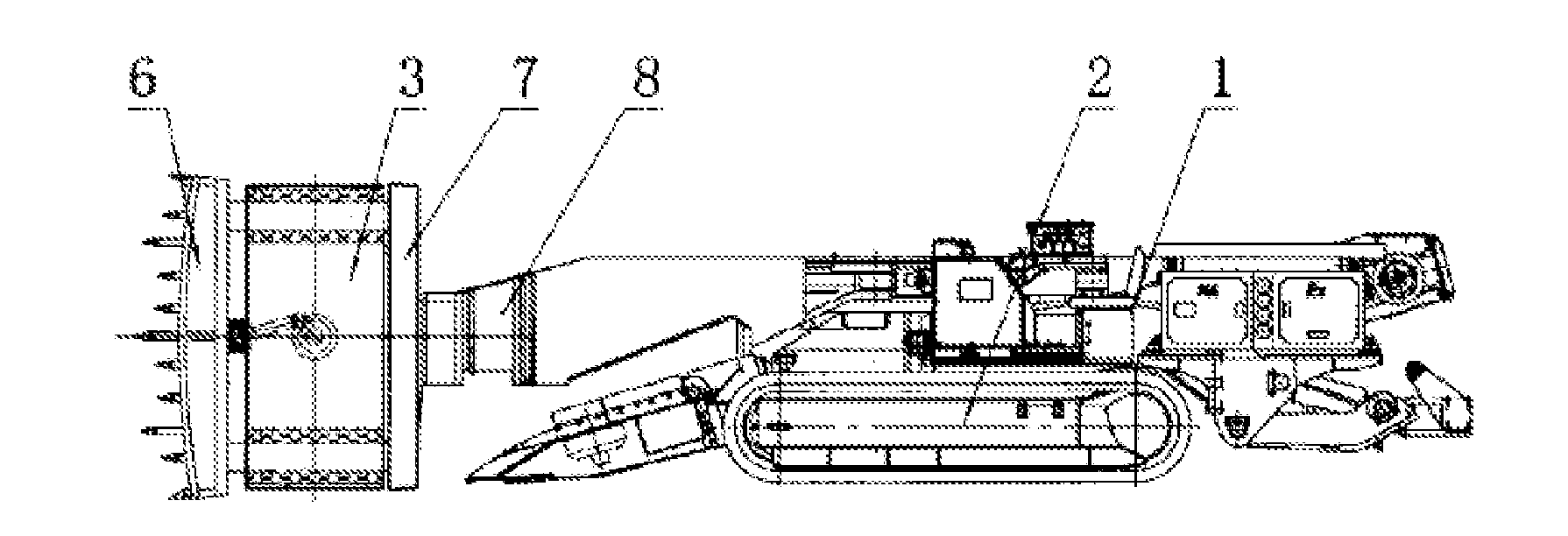
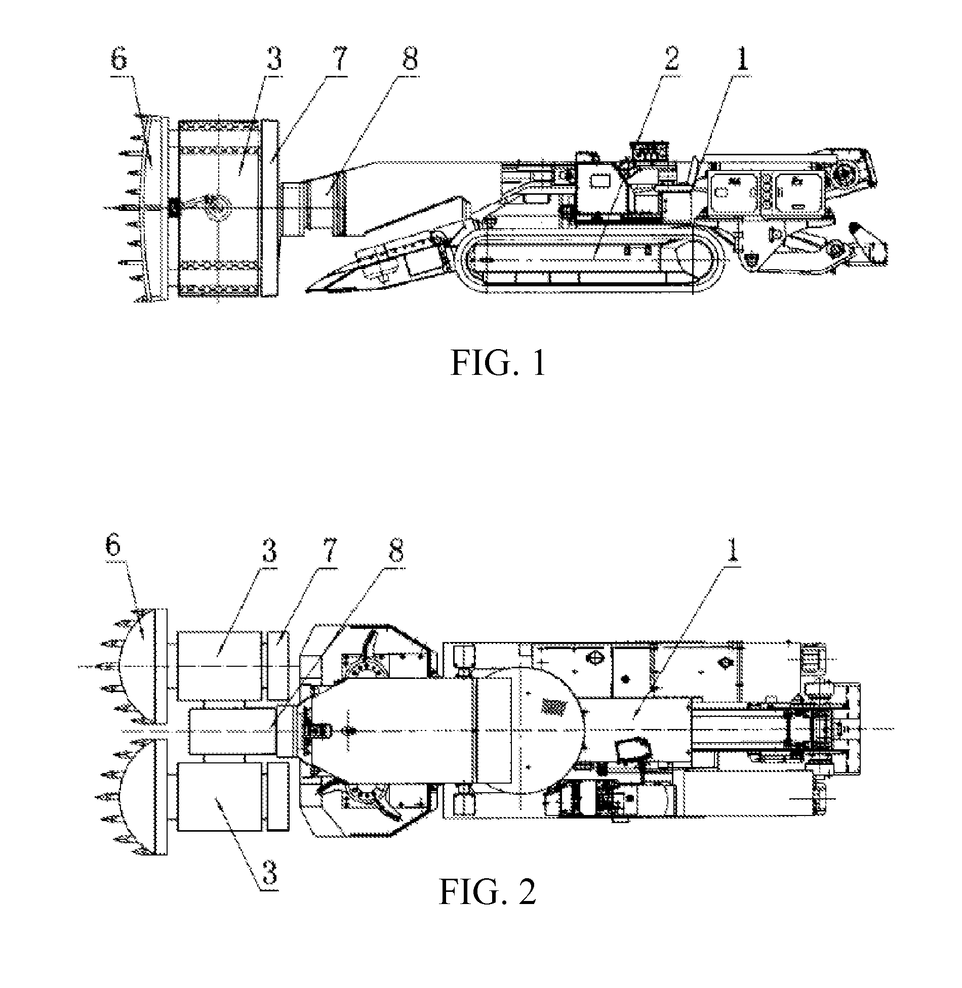
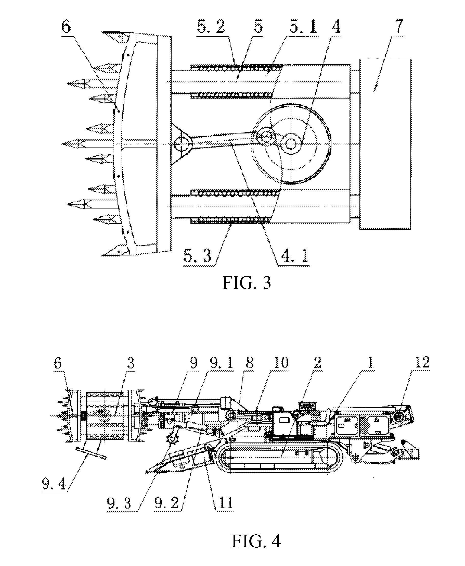
[0297]As shown in FIG. 1 to FIG. 3, a wear-resistant impact mining machine, the rolling friction impact mining machine comprises a machine body 1, a travelling part 2, and a reciprocating impact part 3 etc.; the reciprocating impact part 3 comprises a guiding device 5 and an impact drive device 4 etc.; the guiding device 5 and the impact drive device 4 are separated; the guiding device 5 comprises an impact guiding element 5.1, guiding rollers 5.3 and a guiding support 5.2 etc.; the guiding rollers 5.3 are provided between the guiding support 5.2 and the impact guiding element 5.1; one end of the impact guiding element 5.1 is provided with an impact head 6 and the other end is provided with a counterweight element 7 for preventing the impact head 6 from damaging the guiding device 5, the impact drive device 4 and / or the machine body 1 etc. due to gravity unbalance; the impact head 6 is connected with the impact guiding element 5.1; the impact drive device 4 comprises a power impact ...

embodiment 2

[0311]As shown in FIG. 4 to FIG. 5, a wear-resistant impact mining machine, the rolling friction impact mining machine comprises a machine body 1, a travelling part 2, and a reciprocating impact part 3 etc.; the reciprocating impact part 3 comprises a guiding device 5 and an impact drive device 4 etc.; the guiding device 5 and the impact drive device 4 are integrated; the guiding device 5 comprises an impact guiding element 5.1, guiding rollers 5.3 and a guiding support 5.2 etc.; the guiding rollers 5.3 are provided between the guiding support 5.2 and the impact guiding element 5.1; two ends of the impact guiding element 5.1 are provided with impact heads 6 etc.; the impact heads 6 and the impact guiding element 5.1 are integrated; the impact drive device 4 comprises a power impact element 4.1 etc.; the power impact element 4.1 drives the impact guiding element 5.1 to reciprocate; the impact guiding element 5.1 drives the impact heads 6 to impact a coal wall or a rock wall to fall a...

embodiment 3

[0322]As shown in FIG. 6 to FIG. 7, a wear-resistant impact mining machine comprises a machine body 1, a travelling part 2, a jacking device 9 and a reciprocating impact part 3 etc.; the reciprocating impact part 3 comprises a guiding device 5 and an impact drive device 4 etc.; the impact drive device 4 comprises a crank impact drive device 4.2 or a hydraulic impact drive device or a pneumatic impact drive device etc.; the crank impact drive device 4.2 or the hydraulic impact drive device or the pneumatic impact drive device comprises a power impact element 4.1 etc.; the guiding device 5 comprises a guiding support 5.2, an impact guiding element 5.1 and guiding rollers 5.3 etc.; the guiding rollers 5.3 are provided between the guiding support 5.2 and the impact guiding element 5.1; one end of the impact guiding element 5.1 is provided with an impact head 6 and the other end is provided with a counterweight element 7 for preventing the impact head 6 from damaging the guiding device 5...


PUM


Abstract

A rolling friction or suspension friction impact mining method and a wear-resistant impact mining machine using said method. The mining machine comprises a reciprocating impact part (3). The reciprocating impact part comprises an impact drive device (4), a rolling reciprocating device, and an impact head (6). The rolling reciprocating device comprises a rubbing body (38), a rubbing body support (39), an impact guiding element (5.1), and a position-limiting mechanism. The rubbing body (5.3) are disposed between the robbing body support (39) and the impact guiding element (5.1), and inside of the position-limiting mechanism to form rolling guiding. The impact drive device is disposed with a damage-prevention mechanism, a rotary power buffer device, and a structural buffer device, such that the impact head reciprocatingly move and have rolling or suspending friction under the support of the impact guiding element, thereby preventing the damage-prevention force to damage a power drive device and a rolling channel guiding device, and preventing the impact vibration caused by the reciprocating impact part to affect the machine body and other parts. The overall stability is therefore enhanced, and the service life is extended.

Description

TECHNICAL FIELD OF THE INVENTION[0001]The present invention belongs to the mechanical field, and is especially applicable to a rolling friction or suspension friction impact mining method in the mining field and a wear-resistant impact mining machine using said method.BACKGROUND OF THE INVENTION[0002]Tunneling machines and coal mining machines are mainly applied to excavation of railways, bridges and culverts of roads and tunnels and mechanical mining of ore materials. Most mining machines broadly applied at present are drilling and milling cutting-type tunneling machines and rolling milling cutting-type mining machines and the working principle is to drill and cut or mill and cut in a rolling manner a coalbed or a rockbed through picks arranged on the outer surface at a front part of a cutting head. Since a relatively large rotating damage force is generated by the cutting head during drilling and milling or rolling milling and cutting, a relatively large twisting force will be gen...

Claims


Application Information

Patent Timeline
Patent Type & Authority Applications(United States)
IPC IPC(8): E21C27/46E21D9/10
CPCE21D9/106E21C27/46E21D9/1026E21C27/28
Inventor LIU, SUHUA
Owner LIU SUHUA
Why Eureka
Try Eureka