
Energy-harvesting apparatus and method

a technology of energy harvesting and energy storage, which is applied in the direction of generator/motor, machine/engine, generator, etc., can solve the problems of limiting the efficacy of vibration conversion, resonant frequency, resonant frequency performance, etc., and achieves high performan

Active Publication Date: 2015-05-21
CAMBRIDGE ENTERPRISE LTD
View PDF5 Cites 17 Cited by
  • Summary
  • Abstract
  • Description
  • Claims
  • Application Information

AI Technical Summary

Benefits of technology

The invention is about a new way to harness small vibrations using a parametric resonator. This resonator has the advantage of being able to pick up a wider range of frequencies and can generate higher power than a direct resonator. The invention also includes a mechanism to reduce the energy required to initiate the resonator. By driving the resonator through a mechanical amplifier, it can be made to exceed its initiation pressure threshold. The use of a piezoelectric material in the resonator makes it easy to use existing fabrication techniques. Overall, this invention presents a way to effectively harness small vibrations and improve energy harvesting.

Problems solved by technology

Such conventional energy harvesters suffer from several problems which limit their efficacy for converting vibration energy into electrical energy.
Two problems in particular relate to the performance of the resonator(s).
First, the resonator in a conventional energy harvester has a specific resonant frequency and can only be effectively excited by vibration frequencies close to that resonant frequency.
One approach which has been used to address this is to incorporate into an energy harvester a plurality of direct resonators of different resonant frequencies, but this adds to the complexity of the energy harvester.
Second, the power density storable in a direct resonator is limited as a linear function of the driving vibration amplitude, and this constrains the energy which can be transferred from an input vibration to a resonator in a conventional energy harvester.
But the inventors are aware of only one prior art attempt to investigate the use of parametric resonance for energy harvesting, and this investigation found a significant problem.
The problem reported by Daqaq et al. is that a threshold vibration amplitude is required to excite a parametric resonator, and that as a result, the parametric resonator in their energy harvester could not harvest low-amplitude input vibrations.
This dramatically reduced the energy that could be collected by their harvester.

Method used


Image

  • Energy-harvesting apparatus and method
  • Energy-harvesting apparatus and method
  • Energy-harvesting apparatus and method

Examples


Embodiment Construction

[0043]The principle of operation of the invention, including description of specific embodiments of the invention, will now be described in more detail with reference to the accompanying drawings in which;

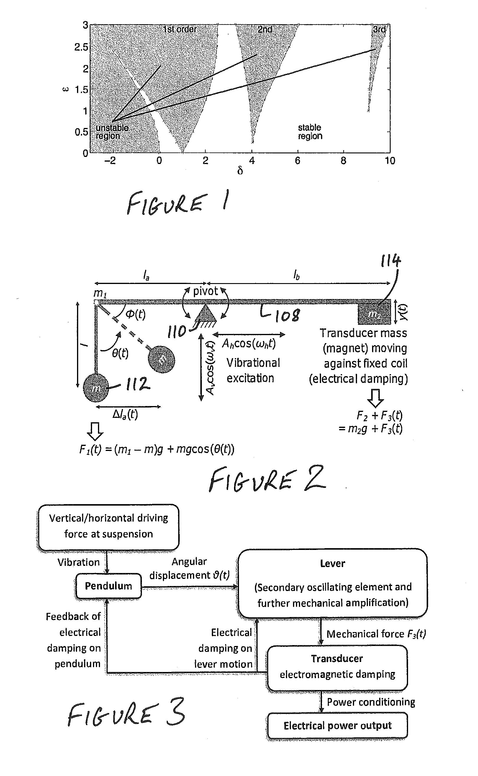
[0044]FIG. 1 is a graph showing stable (unshaded) and unstable (shaded) regions in the δ-ε parameter plane of the Mathieu equation (numerically generated). The unstable region signifies the achievement of parametric resonance;

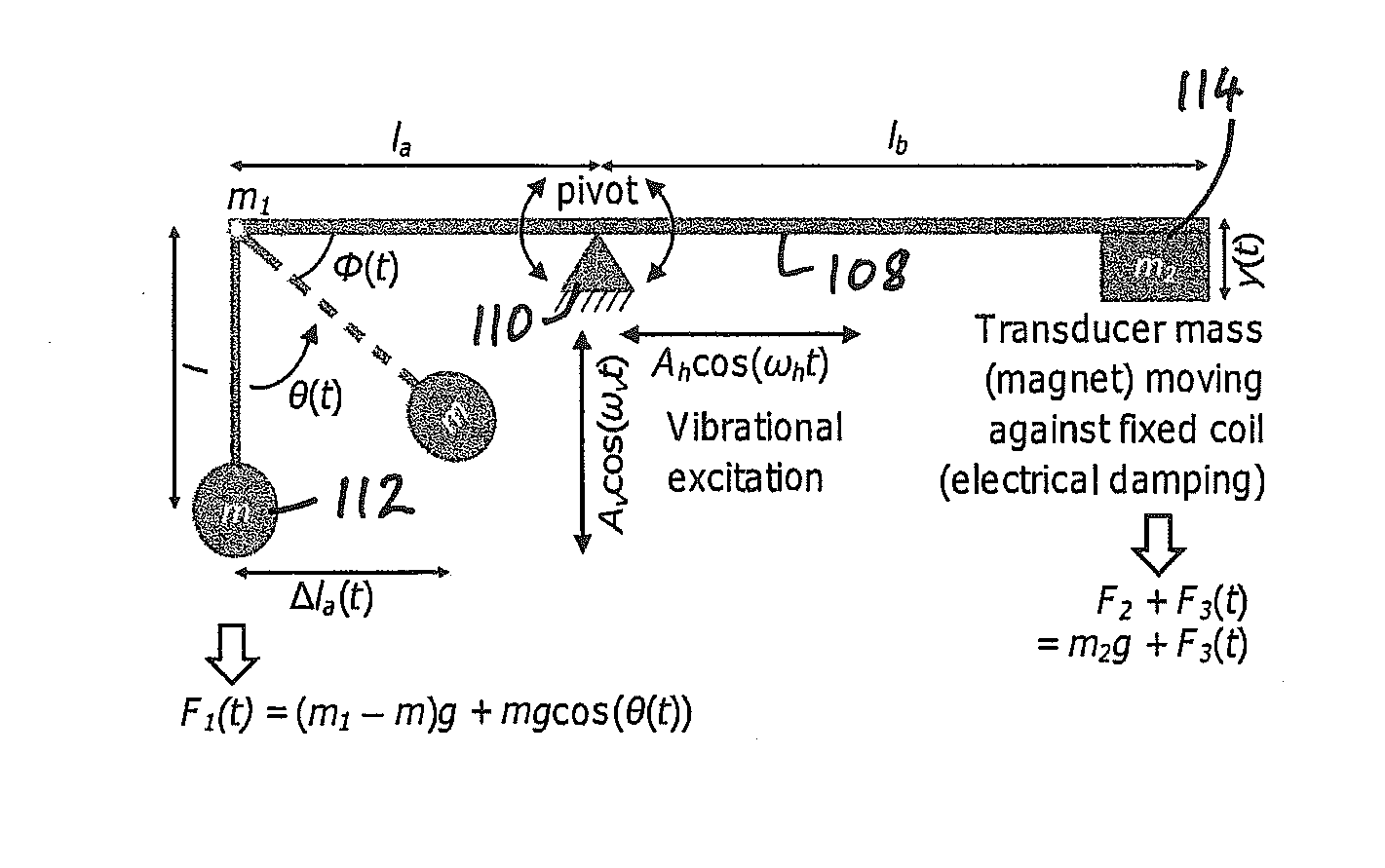
[0045]FIG. 2 is a schematic diagram of a Parametrically Excited Vibration Energy Harvester (PEVEH) embodiment. Vertical driving force yields parametric excitation;

[0046]FIG. 3 is a block diagram illustrating the overall structure of a MATLAB numerical model constructed, as described below;

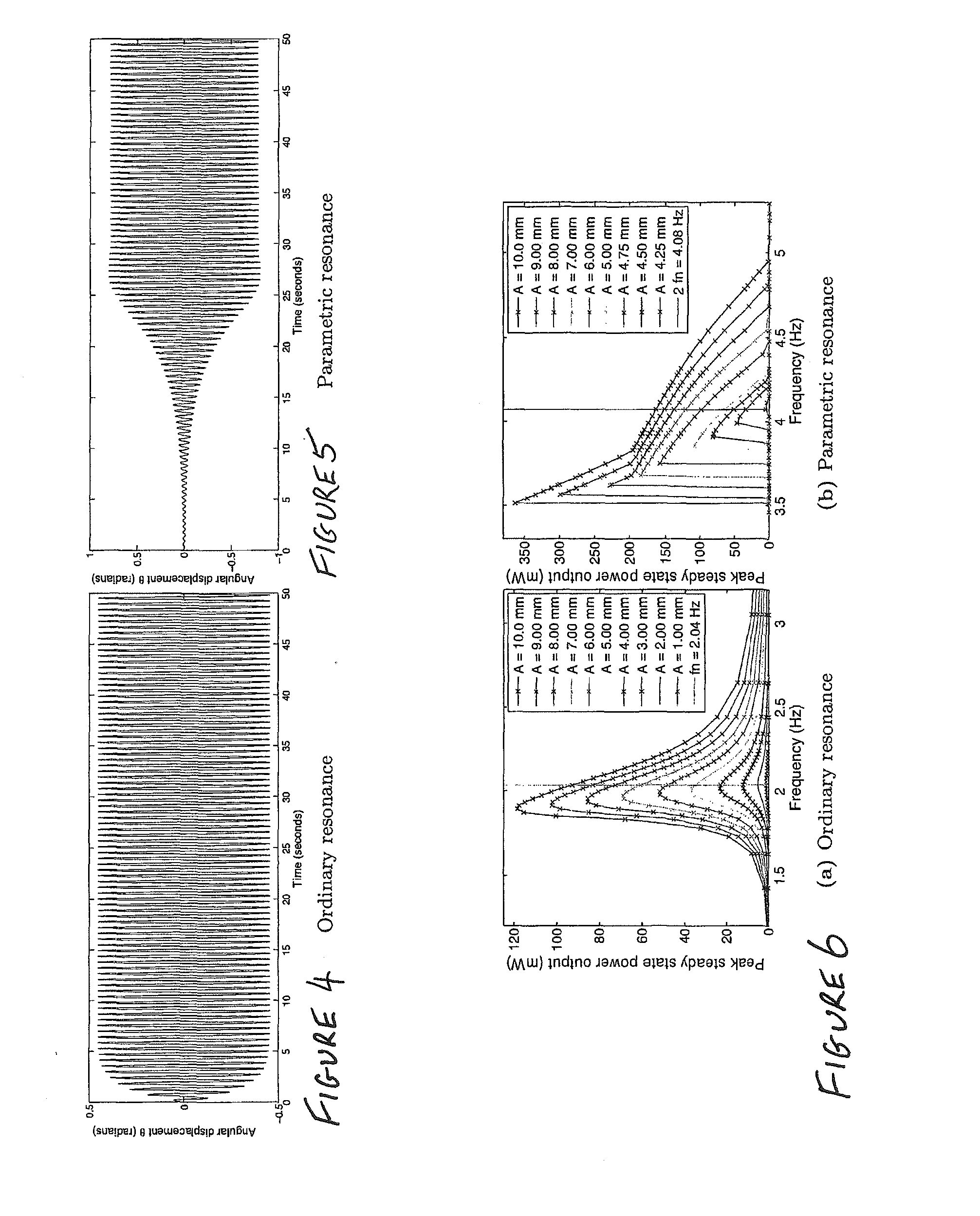
[0047]FIGS. 4 and 5 illustrate numerical simulations of the oscillatory amplitude build up (in time domain) for the embodiment of FIG. 2 near critical damping. FIG. 4 relates to excitation of ordinary resonance and FIG. 5 relates to parametric resonance. In this case, paramet...


PUM


Abstract

An energy harvester is provided for harvesting energy, and in particular electrical energy from an input vibration such as an ambient vibration. The energy harvester comprises a first mechanical amplifier responsive to the input vibration and a second mechanical amplifier coupled to the first mechanical amplifier. At least one of the first and second mechanical amplifiers comprises a parametric resonator, and a power output of the energy harvester is generated by damping the second mechanical amplifier.

Description

[0001]The invention relates to an energy-harvesting apparatus and method, for harvesting or collecting energy from a source of vibration, such as ambient or environmental vibration.[0002]In a conventional energy harvester a direct resonator, or in some cases a plurality of direct resonators, is responsive to an input vibration, such as vibration of a structure to which the energy harvester is attached. (In the art, direct resonators may also be termed linear, or ordinary, resonators.) The vibration excites the resonator(s) and the resonator(s) are electrically damped, for example by means of a permanent magnet carried by a resonator so that it oscillates in the proximity of a conducting coil, to extract an electrical power output. Such energy harvesters can be used to charge a battery or to operate an electronic device such as a sensor and / or a wireless transmitter in a self-contained device, in known manner.[0003]Such conventional energy harvesters suffer from several problems whic...

Claims


Application Information

Patent Timeline
Patent Type & Authority Applications(United States)
IPC IPC(8): H02N2/18F03G7/08H02K7/18H10N30/20H10N30/30H10N30/87
CPCH02N2/188F03G7/08H02K7/1892H02K35/02Y10T74/18856H10N30/306
Inventor JIA, YUYAN, JIZESESHIA, ASHWIN ARUNKUMARSOGA, KENICHI
Owner CAMBRIDGE ENTERPRISE LTD
Learn More