Facilitated co2 transport membrane and method for producing same, and method and apparatus for separating co2

a co2 transport membrane and co2 technology, applied in the direction of hydrogen separation using solid contact, metal/metal-oxide/metal-hydroxide catalyst, etc., can solve the problem of difficult to allow selective passage of gases having a larger molecular diameter, wasteful energy consumption, and difficulty in reducing the cost of natural energy, etc. problem, to achieve the effect of improving co2/h2 selectivity, facilitating co2 transport membrane, and improving co2 permean

Active Publication Date: 2015-06-04
RENAISSANCE ENERGY RES
View PDF3 Cites 11 Cited by
  • Summary
  • Abstract
  • Description
  • Claims
  • Application Information

AI Technical Summary

Benefits of technology

[0045]According to the facilitated CO2 transport membrane having the above-mentioned features and the method for producing the same, a facilitated CO2 transport membrane having an improved CO2 permeance and an improved CO2 / H2 selectivity can be stably supplied. Particularly, the CO2 hydration catalyst has catalytic activity at a temperature of 100° C. or higher, so that a facilitated CO2 transport membrane that is applicable at a high temperature of 100° C. or higher and capable of achieving high selective permeability to hydrogen can be stably supplied in a decarbonation step in a hydrogen production process or the like.
[0046]Further, according to the CO2 separation method and apparatus having the above-mentioned features, a facilitated CO2 transport membrane having high selective permeability to hydrogen at a high temperature of 100° C. or higher is used, so that CO2 can be selectively separated with high efficiency from a mixed gas containing CO2 and H2 and having a temperature of 100° C. or higher.

Problems solved by technology

A chemical absorption method that is used in a decarbonation processes in existing large-scale plants such as hydrogen production plants and ammonia production plants requires a huge CO2 absorption tower and a huge regeneration tower for a CO2 absorbing liquid in order to separate CO2, and in a regeneration step for the CO2 absorbing liquid, requires a large amount of steam for heating the CO2 absorbing liquid to remove CO2 therefrom so that the liquid absorbing CO2 can be reused, and therefore energy is wastefully consumed.
In recent years, as a countermeasure for global warming, natural energy that does not emit CO2 has been expected to come into wide use, but natural energy has a significant problem in terms of cost.
Since the diffusion coefficient increases as the molecular diameter decreases, and the contribution of diffusivity selectivity is generally greater than that of solubility selectivity in gas separation, it is difficult to allow selective passage of gases having a larger molecular diameter by suppressing passage of gases having a smaller molecular diameter among multi-component gases having different molecular diameters.
Therefore, it is extremely difficult to prepare a CO2 selective permeable membrane that separates, particularly from a mixed gas containing H2 and CO2, CO2 with high selectivity to H2 having the smallest molecular diameter among gas molecules.
It is still more difficult to prepare a CO2 selective permeable membrane that is capable of being put to practical use in a decarbonation process in a hydrogen production plant or the like and that functions at a high temperature of 100° C. or higher.

Method used


Image

  • Facilitated co2 transport membrane and method for producing same, and method and apparatus for separating co2
  • Facilitated co2 transport membrane and method for producing same, and method and apparatus for separating co2
  • Facilitated co2 transport membrane and method for producing same, and method and apparatus for separating co2

Examples


first embodiment

[0057]First, one embodiment of a facilitated CO2 transport membrane and a method for producing the same according to the present invention (hereinafter, referred to as “the present facilitated transport membrane” and “the present production method” as appropriate) will be described with reference to the drawings.

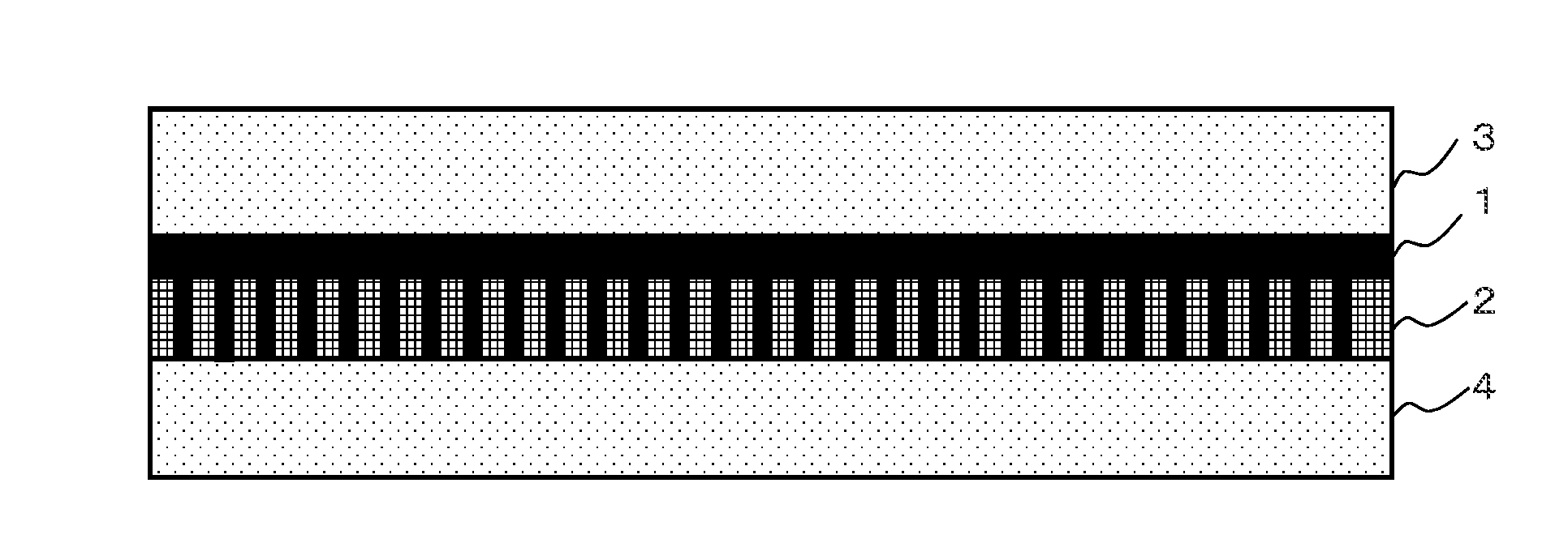
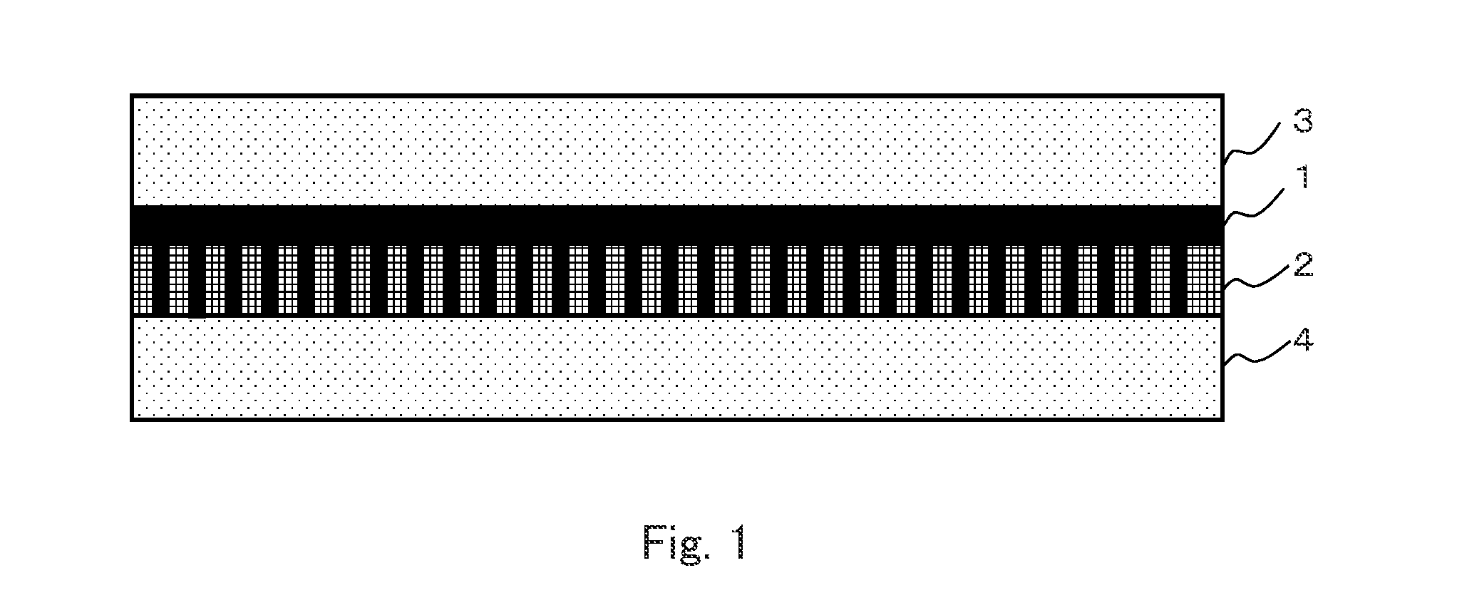
[0058]The present facilitated transport membrane is a facilitated CO2 transport membrane including a separation-functional membrane that includes a water-containing hydrophilic polymer gel membrane containing a CO carrier and a CO2 hydration catalyst having catalytic activity at a temperature of 100° C. or higher, the facilitated CO2 transport membrane serving at a temperature of 100° C. or higher and having a high CO permeance and a high CO2 / H2 selectivity, and the facilitated CO2 transport membrane being applicable to a CO2 permeable membrane reactor or the like. Further, for stably achieving a high CO2 / H2 selectivity, the present facilitated transport membrane includes a ...

second embodiment

[0110]A CO2 separation apparatus and a CO2 separation method, to which the facilitated CO2 transport membrane described in the first embodiment is applied, will now be described with reference to FIGS. 9A and 9B.

[0111]FIGS. 9A and 9B are each a sectional view schematically showing an outlined structure of a CO2 separation apparatus 10 of this embodiment. In this embodiment, as an example, a facilitated CO2 transport membrane modified into a cylindrical structure is used instead of the facilitated CO2 transport membrane of flat plate structure described in the first embodiment. FIG. 9A shows a cross section structure at a cross section perpendicular to the axial center of a facilitated CO2 transport membrane (the present facilitated transport membrane) 11 of cylindrical structure, and FIG. 9B shows a cross section structure at a cross section extending through the axial center of the present facilitated transport membrane 11.

[0112]The present facilitated transport membrane 11 shown i...


PUM

PropertyMeasurementUnit
temperatureaaaaaaaaaa
melting pointaaaaaaaaaa
hydrophilicaaaaaaaaaa

Abstract

Provided is a facilitated CO2 transport membrane having an improved CO2 permeance and an improved CO2/H2 selectivity. The facilitated CO2 transport membrane includes a separation-functional membrane that includes a hydrophilic polymer gel membrane containing a CO2 carrier and a CO2 hydration catalyst. Further preferably, the CO2 hydration catalyst at least has catalytic activity at a temperature of 100° C. or higher, has a melting point of 200° C. or higher, or is soluble in water.

Description

CROSS-REFERENCE TO RELATED APPLICATIONS[0001]This application is a National Phase filing under 35 U.S.C. §371 of International Application No. PCT / JP2013 / 076665 filed on Oct. 1, 2013, and which claims priority to Japanese Patent Application No. 2012-220250 filed on Oct. 2, 2012.TECHNICAL FIELD[0002]The present invention relates to a facilitated CO2 transport membrane that is used for separating carbon dioxide (CO2), particularly to a facilitated CO2 transport membrane that separates carbon dioxide produced as a by-product in a hydrogen production process or the like at a high selection ratio to hydrogen. The present invention further relates to a method for producing the facilitated CO2 transport membrane, and a method and an apparatus for separating CO2 using the facilitated CO2 transport membrane.BACKGROUND ART[0003]In a hydrogen production process, it is necessary that CO2 produced as a by-product in the course of producing hydrogen be separated and removed from a hydrogen gas.[0...

Claims


Application Information

Patent Timeline
Patent Type & Authority Applications(United States)
IPC IPC(8): B01D53/22B01J27/057B01J23/18C01B3/58B01J20/04B01J20/28B01J20/32B01J20/26B01J23/04C01B32/50
CPCB01D53/228B01J20/265B01J27/0576B01J27/0573B01J23/18B01J23/04C01B2203/0475B01J20/28047B01J20/3231C01B3/58C01B2203/0435C01B2203/0405B01J20/043B01D67/0009B01D69/12B01D69/142B01D69/145B01D71/38B01D2325/36B01D2325/38B01D71/40B01D71/76B01D2325/10B01D71/36B01D2053/223B01D2256/16B01D2257/504C01B2203/0233C01B2203/0283C01B3/503B01J20/264Y02P20/151Y02C20/40C01B32/50B01D53/22B01D67/00B01D69/00B01D71/02B01D69/10C01B2203/0238
Inventor OKADA, OSAMUHANAI, NOBUAKIYAN, PENGMIYATA, JUNYAKIYOHARA, YASATOISHII, SAYAKANAGANO, MEGUMI
Owner RENAISSANCE ENERGY RES
Why Eureka
Try Eureka