Acidic gas separation module and production method therefor, acidic gas separation layer, production method and facilitated transport membrane therefor, and acidic gas separation system

Inactive Publication Date: 2015-06-04
FUJIFILM CORP
View PDF35 Cites 23 Cited by
  • Summary
  • Abstract
  • Description
  • Claims
  • Application Information

AI Technical Summary

Benefits of technology

The patent describes a new acidic gas separation layer, module, and system that addresses the problem of low efficiency and deterioration of membranes in separating acidic gases from materials containing water vapor at high temperatures. The new layer suppresses the delichts (ability to absorb moisture) of a facilitated transport membrane, while maintaining high separation performance and excellent production and usability. This new technology can facilitate the process of separating acidic gases from gas mixtures.

Problems solved by technology

Particularly, in the separation of an acidic gas from a material gas containing water vapor at a high temperature of 100° C. or higher, the dissolution-diffusion membrane and the adhesive portion are deteriorated by heat and moisture, so that the separation efficiency is reduced.
In the acidic gas separation module disclosed in the specification of Japanese Patent No. 4621295, although a facilitated transport membrane is used as the acidic gas separation membrane, since this membrane is arranged inside a tube, it is difficult to increase the membrane surface area.
Therefore, unless the number of modules is increased, the acidic gas separation efficiency remains low.
Meanwhile, since this membrane requires mediation by water, its deliquescent properties present a problem.
Consequently, the ease of handling the membrane in the preparation of an acidic gas separation module is deteriorated and the production suitability is thus impaired.
In addition, excessive deliquescence is a factor that interferes with the gas separation operation.

Method used


Image

  • Acidic gas separation module and production method therefor, acidic gas separation layer, production method and facilitated transport membrane therefor, and acidic gas separation system
  • Acidic gas separation module and production method therefor, acidic gas separation layer, production method and facilitated transport membrane therefor, and acidic gas separation system
  • Acidic gas separation module and production method therefor, acidic gas separation layer, production method and facilitated transport membrane therefor, and acidic gas separation system

Examples


modification examples

[0340]Thus far, a specific embodiment of the present invention has been described in detail; however, the invention is not restricted thereto by any means. It is obvious to those of ordinary skill in the art that other various embodiments are possible within the scope of the invention and, for example, the above-described embodiment may be combined with any of the below-described modification examples as appropriate, or the above-described embodiment may be replaced with any of the below-described modification examples.

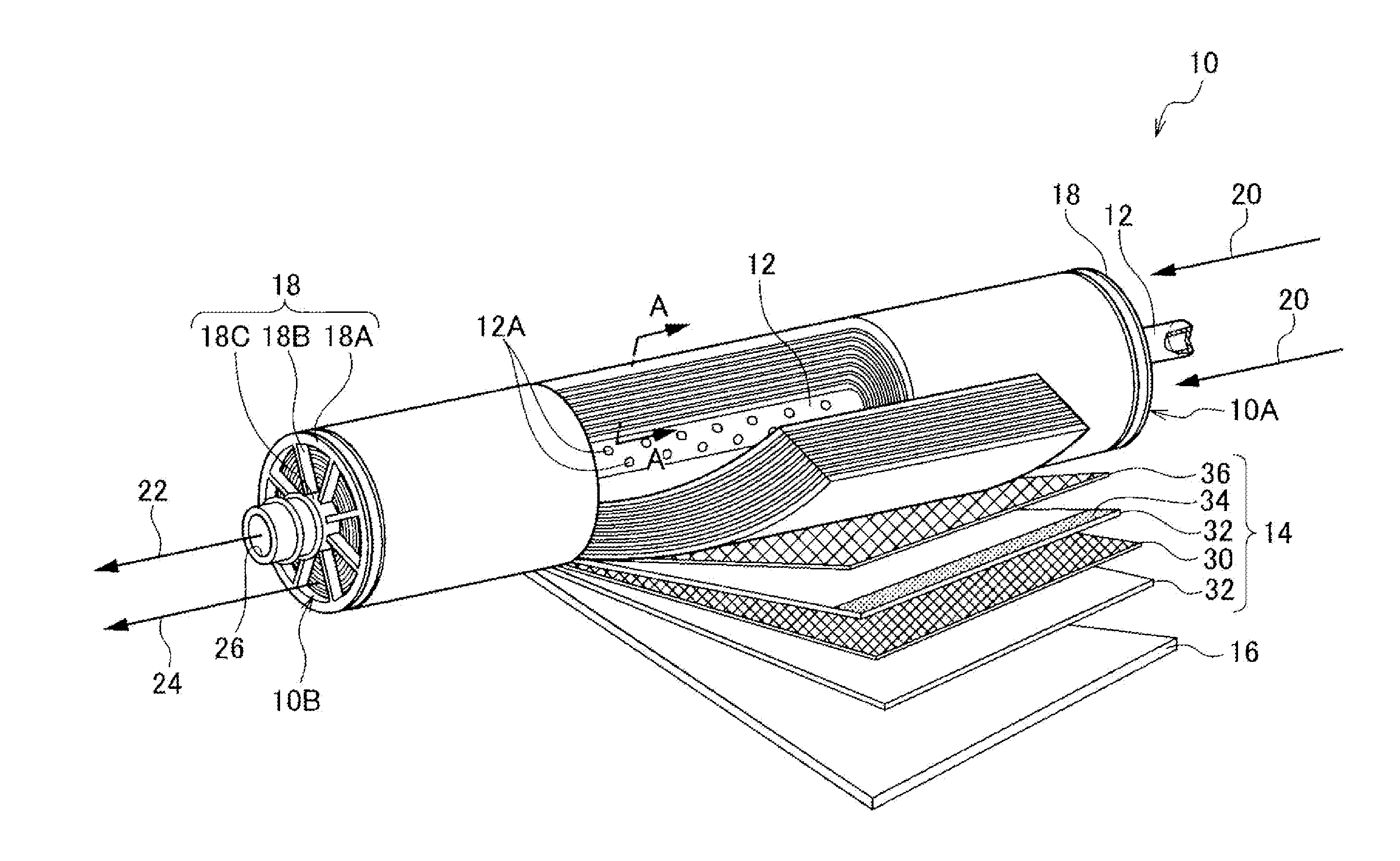
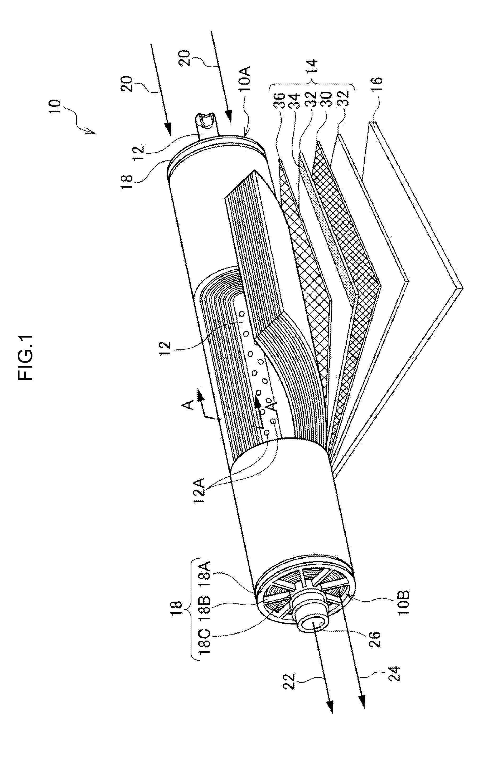
[0341]For example, in the above-described embodiment, a case where the acidic gas separation module 10 is constituted such that the acidic gas-containing material gas 20 fed from the side of one end 10A thereof to the layered body 14 is separated into the acidic gas 22 and the residual gas 24, which are then separately discharged to the side of the other end 10B, was explained. However, the acidic gas separation module 10 may also be constituted such that the acidic g...

example 1

[0360]In Example 1, after adding 1M hydrochloric acid to an aqueous solution containing 2.4% by weight of KURASTOMER AP-20 (manufactured by KURARAY Co., Ltd.) and 0.01% by weight of a 25% aqueous glutaraldehyde solution (manufactured by Wako Pure Chemical Industries, Ltd.) to a pH of 1 and thereby performing cross-linking, a 40% aqueous cesium carbonate solution (manufactured by Kisan Kinzoku Chemicals Co., Ltd.) was added as a carrier to the resultant to a cesium carbonate concentration of 6.0% by weight. Further, 1% RAPISOL A-90 [manufactured by NOF Corporation; a surfactant having the structure represented by the above-described Formula (1) (sodium di(2-ethylhexyl) sulfosuccinate: molecular weight=445; specific compound)] was added in an amount of 0.003% by weight. Then, the resulting mixture was heated and an aqueous agar solution, which had been separately prepared, was added thereto to prepare a coating composition.

[0361]Using a PTFE / PP nonwoven fabric (manufactured by GE) as ...

example 2

[0369]An acidic gas separation module of Example 2 was prepared in the similar manner as in Example 1, except that the ratio of the pores of the porous support that were impregnated with the adhesive was changed to 86%. This module had a membrane surface area of 0.025 m2.


PUM

PropertyMeasurementUnit
Fractionaaaaaaaaaa
Percent by massaaaaaaaaaa

Abstract

Provided is an acidic gas separation module 10 which contains: a permeated gas collection tube 12 having through-hole 12As formed on the wall thereof; a layered body 14 in which a feed gas flow path member 30 through which an acidic gas-containing source gas is fed, an acidic gas separation layer 32 that contains a carrier reacting with the acidic gas and a hydrophilic compound supporting the carrier, and a permeated gas flow path member 36 through which the acid gas that has reacted with the carrier and permeated through the acidic gas separation layer 32 flows toward the through-hole 12As are layered; and heat / moisture-resistant adhesive parts 34 and 40 which adhere the both side edges of the acidic gas separation layer 32 and the permeated gas flow path member 36 along the circumferential direction in a state where the layered body 14 is wound in layers on the permeated gas collection tube 12, the adhesive parts 34 and 40 also adhering the circumferential direction edges of the acidic gas separation layer 32 and the permeated gas flow path member 36.

Description

CROSS-REFERENCE TO RELATED APPLICATIONS[0001]This application is a continuation application of International Application No. PCT / JP2013 / 066634, filed Jun. 17, 2013, the disclosure of which is incorporated herein by reference in its entirety. Further, this application claims priority from Japanese Patent Applications No. 2012-139001 filed on Jun. 20, 2012, No. 2012-198702 filed on Sep. 10, 2012, and No. 2013-067015 filed on Mar. 27, 2013, the disclosures of which are incorporated herein by reference in its entirety.BACKGROUND[0002]1. Technical Field[0003]The present invention relates to: an acidic gas separation module and a production method thereof; an acidic gas separation layer, a production method and a facilitated transport membrane thereof; and an acidic gas separation system.[0004]2. Related Art[0005]In recent years, an advance has been made in the technology for selective separation of an acidic gas contained in a material gas. For example, acidic gas separation modules, whi...

Claims


Application Information

Patent Timeline
IPC IPC(8): B01D53/22B01J20/26B01J20/32B01J20/04
CPCB01D53/228B01J20/043B01D2053/223B01J20/3234B01J20/26B01D69/10B01D61/38B01D63/103B01D69/142B01D2311/13B01D2313/086B01D2323/46B01D2256/16B01D2257/504Y02C20/40B01D69/107B01D69/108B01D53/22
Inventor ISHIZUKA, KENICHI
Owner FUJIFILM CORP
Why Eureka
Try Eureka