Blow Moulded Bottle, Method of Manufacturing and Mould

a bottle and blow molding technology, applied in the field of bottle construction, can solve the problems of difficult lifting and manoeuvre, poor mechanical resistance, and inability to manufacture by blow molding bottles, etc., and achieve the effects of less stretching, good mechanical resistance, and high crystallisation ra

Inactive Publication Date: 2015-06-04
DES EAUX MINERALES DEVIAN
View PDF3 Cites 7 Cited by
  • Summary
  • Abstract
  • Description
  • Claims
  • Application Information

AI Technical Summary

Benefits of technology

[0102]According to an outstanding feature, the (annular) base joining the terminal curved portion to the dome, has high crystallisation rate, according to the below definition. Therefore, this area exposed to mechanical shocks and constraints has a good mechanical resistance.
[0103]According to another outstanding feature, the dome is amorphous because the end of the preform is less stretched, and thus exhibits a low crystallisation rate and lower mechanical resistance, according to the below definition.
[0104]In a such integral bottom structure, the terminal curved portion makes it possible to protect the bottle against the shocks, especially with respect to the dome which is usually amorphous, considering the manufacture processes, wherein the dome area is generally not stretched and thus not transformed from the amorphous state to the crystalline state.

Problems solved by technology

They are difficult to lift and manoeuvre into position on the cooler unit because of their bulk and weight when full.
Because these jugs are returnable and refillable, they are thus subjected to numerous handling and storage operations and conditions, wherein they are exposed to mechanical constraints such as abrasive wear, notably in the contact area between the jugs after stacking, or such as drops.
But the polycarbonate is a heavy and expensive raw material and also as polycarbonate is made from bisphenol A and as bisphenol A is an endocrine disruptor, polycarbonate could be forbidden for making beverage containing jugs.
The polyesters such as Polyethylene Terephtalate (PET) is suitable as far as the weight and the cost are concerned but they do not make it possible to manufacture by molding (especially blow molding) bottles resistant to scuffing and to shocks.
These prior references propose technical solutions which could be adapted to give a good resistance to pressure but which are not satisfactory notably with regards to the above mentioned requirements: (i) Resistance to abrasion (scuffing) and (ii) Impact or drop resistance.

Method used


Image

  • Blow Moulded Bottle, Method of Manufacturing and Mould
  • Blow Moulded Bottle, Method of Manufacturing and Mould
  • Blow Moulded Bottle, Method of Manufacturing and Mould

Examples


example

[0191]20 litres jugs are manufactured by injection and blowing with a shell mold in aluminium (3 parts). Vent holes of 5 mm have been done in the etching area and 0.3 mm in the engraving area. The thermoplastic raw material is a Pet resin INVISTA T94.

[0192]The parameters of the process are usual ones. Heat conditioning and preblow step B are implemented.

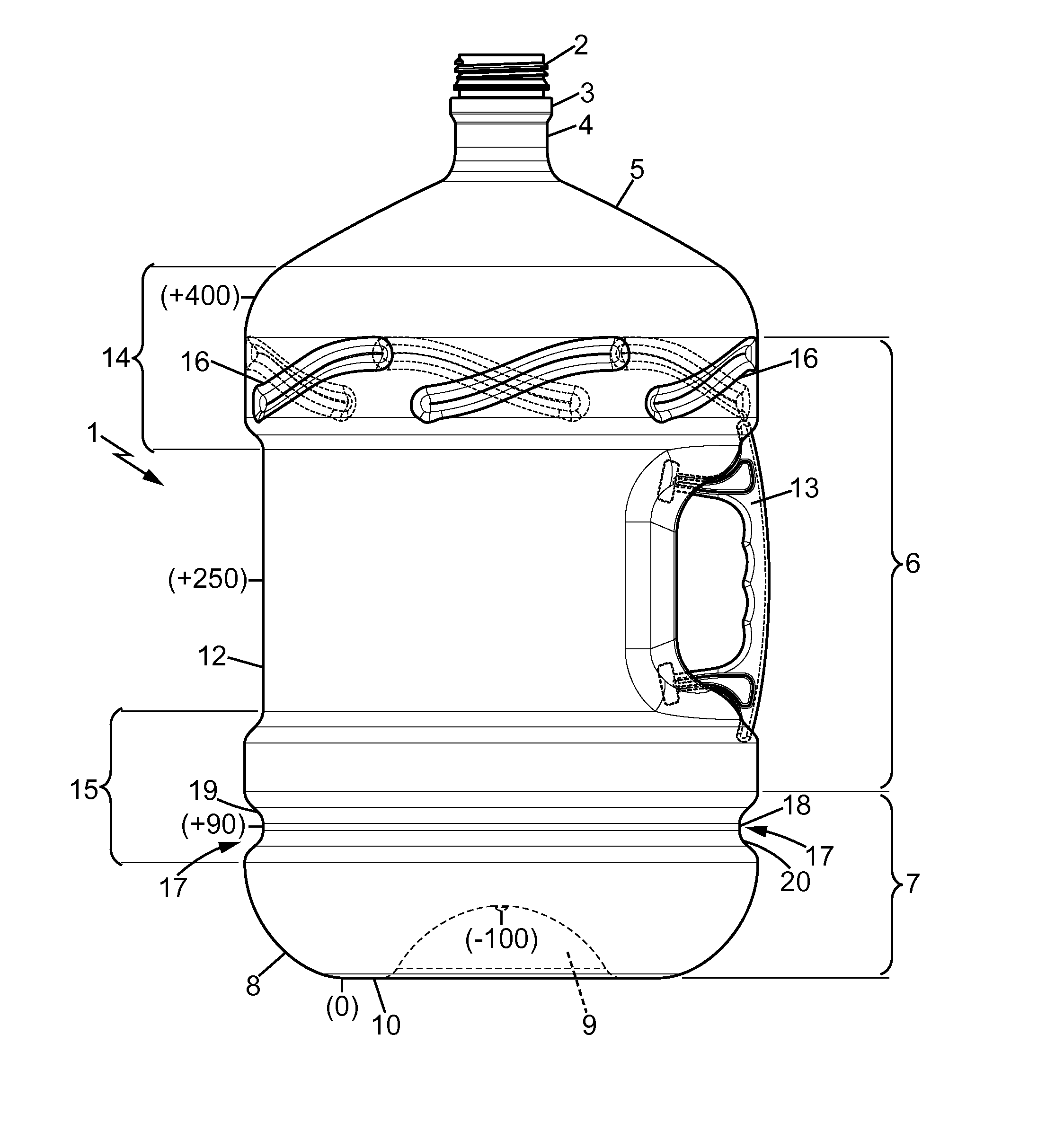
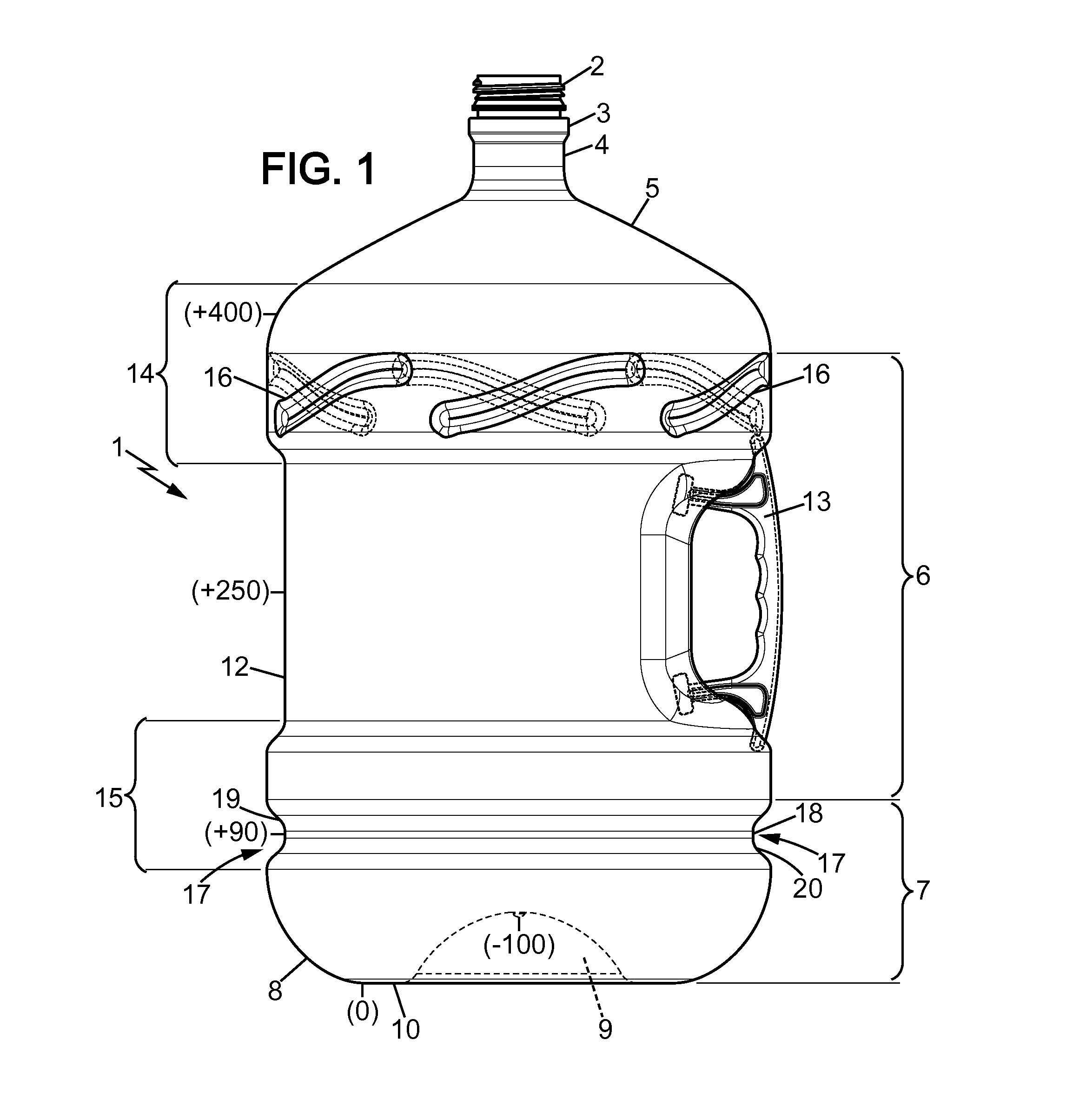
[0193]The dimensions of the preform, the preblow and the jugs are as follows:

PreformPreblowJug(injection(heat conditioning(blowingstep A)step B)step C)Diameter (dt)5575275.5Height (ht)450450496[0194]A handle is injected on a 4 cavities mold on a standard injection press. The raw material of the handle is Polypropylene[0195]The jugs have a good appearance of after blowing[0196]The thickness distribution of the preforms, the preblows, and the jugs is given on FIG. 6.[0197]The resistance to shocks of the jugs is assessed with a drop test.

Protocol Hod Bottles Drop Test

[0198]The objective of this drop test is to measure the resistance of ...


PUM

PropertyMeasurementUnit
thicknessaaaaaaaaaa
thicknessaaaaaaaaaa
thicknessaaaaaaaaaa

Abstract

A blow moulded plastic bottle includes a neck, a shoulder, a tubular body portion, and an integral bottom structure including: a terminal curved portion, an internal axially inwardly directed dome, and an (annular) base joining the terminal curved portion to the dome; wherein: a spline comprises a flat part in the base plane (Pb) onto the bottle rests when it stands up; the height (h1) between (Pb) and the apex of the dome, the height (h2) between (Pb) and the spline diametral median plane (Pd) which is in the middle of the spline (17) and which is parallel to (Pb), and the maximum external diameter (Dm) of the tubular body portion, being so that [(h1)/(Dm)]*100 is comprised between 14.0 and 16.0% and (h1)<(h2)≦3.5(h1).

Description

FIELD OF THE INVENTION[0001]This invention relates generally to the construction of a bottle suitable for containing water or other liquids. It is particularly applicable to the construction of bottles for containing water for human consumption (generically drinking water hereafter) and which are used in conjunction with water dispensing units and carrying crates or racks.BACKGROUND OF THE INVENTION[0002]Bottles, also named jugs, which are employed in the servicing of drinking, water dispensing units are customarily cylindrical in form. Such bottles, when applied to units of the electrical or non-electrical type, are inverted and positioned upon the upper portion of the dispensing unit to supply water to an inner reservoir as it is being dispensed. Water is supplied to the reservoir from a replaceable bottle which is inverted on the top of the cooler unit, the neck of the bottle being placed in a funnel-shaped inlet to the reservoir at the top of the dispensing unit. Pumps can also ...

Claims


Application Information

Patent Timeline
Patent Type & Authority Applications(United States)
IPC IPC(8): B65D1/02B29C49/48B29C49/62B29D22/00
CPCB65D1/02B29D22/003B29C49/48B29K2105/253B29L2031/7158B29K2905/02B29K2067/003B29C49/62B65D1/0276B65D23/106B29C49/12B29C49/541B29C2049/2039B65D2501/0027B29C2949/072B29C2949/0773B29C2949/0817B29C2949/0826B29C2949/0829
Inventor DOMINGUEZ, JORGE ALEJANDRO GILFANDEUX, ISABELLELOISEL, VINCENT
Owner DES EAUX MINERALES DEVIAN
Why Eureka
Try Eureka