
Detection device, sensor, electronic apparatus and moving object

a detection device and sensor technology, applied in the direction of pulse automatic control, acceleration measurement using interia forces, instruments, etc., can solve the problems of increasing the size of the delay circuit, increasing the power consumption, and increasing the size of the circui

Active Publication Date: 2015-06-11
SEIKO EPSON CORP
View PDF20 Cites 13 Cited by
  • Summary
  • Abstract
  • Description
  • Claims
  • Application Information

AI Technical Summary

Benefits of technology

This patent describes a circuit configuration that prevents certain parts of a circuit from becoming too big and a method for arranging components in the circuit. This configuration also allows for easier adjustment of the distance between different parts of the circuit, which improves its performance and efficiency.

Problems solved by technology

However, in the technique of JP-A-2012-163477 in which the phase adjustment circuit is configured by the PLL circuit, for example, there are problems in that power consumption increases or the size of the circuit increases.
Accordingly, the number of the delay units increases, which increases the size of the delay circuit.
Also, when a selector that selects a synchronization signal from multi-phase clock signals from the DLL circuit is provided, the circuit area of the selector increases, and the area of an interconnect region of the signal lines that connect the DLL circuit to the selector increases, which increases the size of the detection device.

Method used


Image

  • Detection device, sensor, electronic apparatus and moving object
  • Detection device, sensor, electronic apparatus and moving object
  • Detection device, sensor, electronic apparatus and moving object

Examples


Embodiment Construction

[0062]Hereinafter, preferred embodiments of the invention will be described in detail. The embodiments to be described herein do not limit the content of the invention disclosed in the appended claims. Further, not all components described in the embodiments are essential components of the invention. For example, hereinafter, an example in which a physical quantity transducer is a piezoelectric vibrator (vibration gyroscope) and a sensor is a gyro sensor are described, but the invention is not limited thereto. For example, the invention may be applied to a vibrator (vibration gyroscope) of an electrostatic capacitance detection type formed of a silicon substrate or the like, a physical quantity transducer, a sensor or the like that detects a physical quantity equivalent to angular velocity information or a physical quantity other than the angular velocity information.

1. Electronic Apparatus, Gyro Sensor

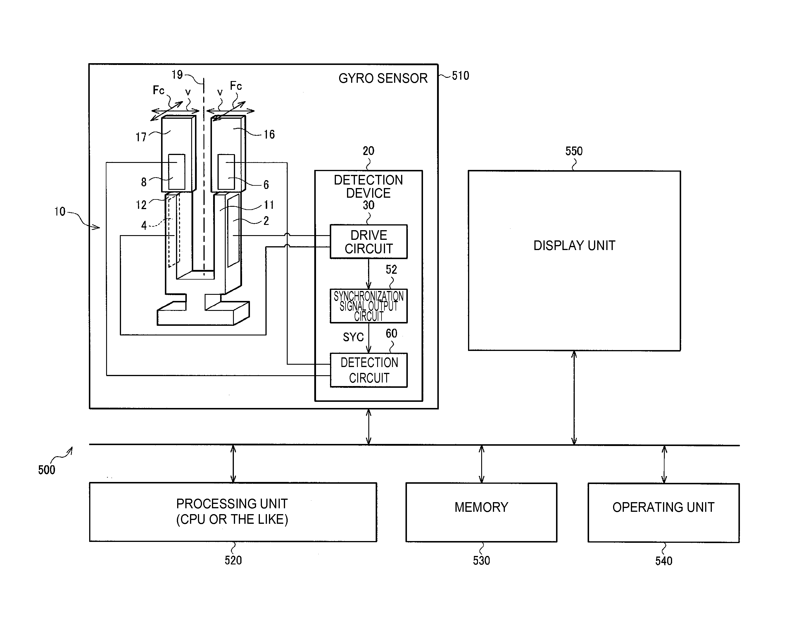
[0063]FIG. 1 shows a configuration example of a gyro sensor 510 (sensor in a broa...


PUM


Abstract

A detection device includes a drive circuit of a physical quantity transducer, a synchronization signal output circuit, and a detection circuit that performs detection of a physical quantity signal based on a physical quantity. The synchronization signal output circuit includes a delay locked loop (DLL) circuit that includes: a delay control circuit that outputs a delay control signal and a delay circuit that includes a plurality of delay units in which a delay time is controlled by the delay control signal; an adjustment circuit that includes at least one delay unit in which a delay time is controlled by the delay control signal, and outputs a signal obtained by delaying an input signal based on the output signal from the drive circuit to the DLL circuit; and an output circuit that outputs the synchronization signal based on multi-phase clock signals from the DLL circuit.

Description

BACKGROUND[0001]1. Technical Field[0002]The present invention relates to a detection device, a sensor, an electronic apparatus, a moving object and the like.[0003]2. Related Art[0004]A gyro sensor for detecting a physical quantity that changes due to external factors is used in electronic apparatuses such as a digital camera or a smart phone, or a moving object such as a vehicle or an airplane. The gyro sensor detects a physical quantity such as an angular velocity, and is used for image stabilization, posture control, GPS autonomous navigation or the like.[0005]For example, a vibration gyro sensor such as a quartz crystal piezoelectric vibration gyro sensor is known as one of the gyro sensors. In the vibration gyro sensor, a physical quantity corresponding to a Coriolis force generated by rotation is detected.[0006]In such a gyro sensor detection device, a synchronization detection circuit for removal of an unnecessary signal is often provided. In order to perform appropriate synch...

Claims


Application Information

Patent Timeline
IPC IPC(8): G01C19/5776H03L7/097G01D5/12H03L7/087
CPCG01C19/5776G01D5/12H03L7/097H03L7/087G01C19/5614H03B5/364H03L7/0814H03L7/0816H03L7/0818
Inventor II, NAOKIMAKI, KATSUHIKOKURASHINA, TAKASHI
Owner SEIKO EPSON CORP
Learn More