Universal water condition monitoring device

Active Publication Date: 2015-06-11
THE UNIVERSITY OF AKRON
View PDF1 Cites 19 Cited by
  • Summary
  • Abstract
  • Description
  • Claims
  • Application Information

AI Technical Summary

Benefits of technology

[0006]One or more embodiments of the present invention provides a novel wireless water condition monitoring device that solves some of the problems found in the existing wireless water condition monitoring devices mentioned above. The approach used in one or more or more embodiments of the present invention significantly reduces the cost of these water condition monitoring devices by eliminating the bulky multiple sensor electrodes, which are a significant drawbacks of exis

Problems solved by technology

The majority of existing water condition monitoring devices are manually operated, hard to use for beginners, and only measure a single condition (only pH or EC), yet are costly with prices ranging from $50 to more than $500.
Moreover,

Method used


Image

  • Universal water condition monitoring device
  • Universal water condition monitoring device
  • Universal water condition monitoring device

Examples


example 1

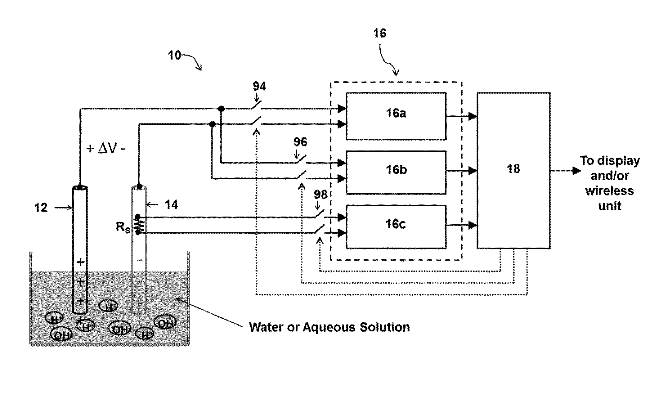
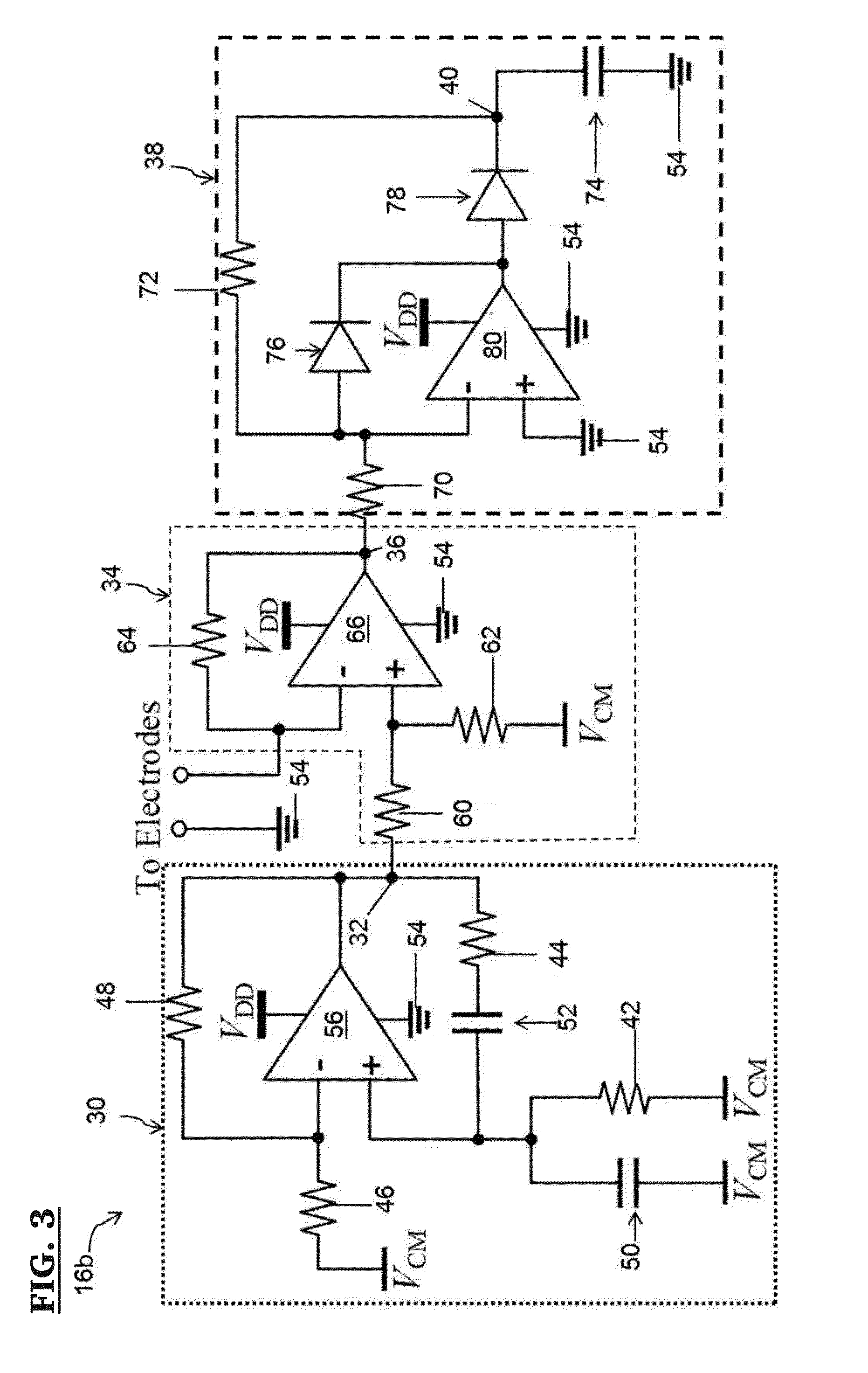
[0064]A prototype of a water condition monitoring device according to one or more embodiments of the present invention was created with a 2 layer printed circuit board (PCB) that included a pH sensor circuit, an EC sensor circuit, a micro controller and the LCD display. A 9V battery was used as the main power source with two additional regulators that generated 3.3V and 5V from the 9V supply to power the sensor circuits, micro controller and LCD. In addition, an RAJ11 interface was implemented to enable on board microcontroller programming. A variable resistor was used for R4 and R5 of the EC circuit (See 38 (R4) and 60 (R5) on FIG. 3) to tune the oscillation frequency and adjust the amplitude of the AC voltage that was applied between the sensor electrodes. This can adjust the dynamic range and resolution of the EC circuit depending on the application conditions.

[0065]In order to measure the pH and EC using the sensor electrodes were placed in 300 ml of distilled water. For EC test...

example 2

[0066]In order to confirm that the output voltage of the proposed EC sensor corresponded to the actual EC value of a water sample, a commercial EC meter was used to map the sensor voltage to the EC value. The EC of the solution was changed from 0.1 siemens to 3.0 siemens, which is the general range for hydroponic applications, and the output voltage of the prototype EC sensor corresponding to the commercial EC meter readings were recorded. A relationship was found between the actual EC value and the proposed sensor output voltage. Based on the relationship between the sensor output voltage and the EC value, a curve fit equation is obtained. That is:

VEC=m*EC+VEC0  (7)

where m is the slope (m=0.3852), VEC0 is the sensor output voltage for EC=0.1 (equal to 1.59V). This VEC is applied to the 10 bit ADC in the microcontroller, which generates digital output corresponding to the input voltage. Since the range of VEC is from 1.59 V to 2.75 V for EC=0.1 to 3.0, assuming a 10-bit ADC (output ...

example 3

[0068]Since the pH is also affected by the nutrient level, to determine the actual pH regardless of nutrient level two different programs were used to determine the pH value depending on the nutrient level (low or high). The nutrient level was determined by the EC, for an EC1.5, high nutrient. In order to determine the output voltage of the proposed sensor corresponding to the actual pH value (first with low nutrient level), a commercial pH meter is used to map the sensor voltage to the actual pH value. The pH of the solution was changed from 5.5 to 8 which is the general range for the hydroponic applications, and the output voltage of the proposed sensor corresponding to the commercial pH meter readings were recorded. A relationship between the actual pH value and the proposed sensor output voltage was found. Based on the relationship between output voltage and pH, a curve fit equation for low nutrient level is obtained. That is:

VpHL=m*pH−VpHL0  (9)

where m is the slope (m=0.115) an...


PUM


Abstract

The present invention is directed to a water condition monitoring device and related methods of use that significantly reduce the cost of the water condition monitoring devices by replacing the expensive and bulky multiple sensor electrodes of currently available devices with a single set of two or three metal electrodes to detect and/or measure such water quality parameters as pH, electric conductivity, temperature, and dissolved oxygen content. A microcontroller activates each sensor one at a time in a continuous loop, processing the sensor signals into near real time water condition data, which may be stored, displayed, or sent to a remote location for storage or display.

Description

CROSS REFERENCE TO RELATED APPLICATIONS[0001]This application claims the benefit of U.S. provisional patent application Ser. No. 61 / 912,604 entitled “Universal Water Condition Monitoring Device,” filed Dec. 6, 2014, and incorporated herein by reference in its entirety.REFERENCE TO GOVERNMENT SUPPORT[0002]The invention was developed at least in part with the support of United States National Science Foundation grant number NSF1000002370 and Ohio Third Frontier TVSF Grant (phase-I) grant number 1000002210ODOD. The government may have certain rights in the invention.FIELD OF THE INVENTION[0003]One or more embodiments of the present invention relates to a device for monitoring water conditions. In certain embodiments, the present invention relates to a device and related method for monitoring pH, temperature, electrical conductivity, and dissolved oxygen content of water using a single set of electrodes.BACKGROUND OF THE INVENTION[0004]Recently, there is an increased demand for user fri...

Claims


Application Information

Patent Timeline
IPC IPC(8): G01N33/18G01N27/02G01K13/00G01N27/30
CPCG01N33/1886G01N27/302G01K13/00G01N33/1853G01N27/02G01K7/16G01N27/06G01N33/18
Inventor LEE, KYE-SHINMAHAJAN, AJAY
Owner THE UNIVERSITY OF AKRON
Why Eureka
Try Eureka