
Sensor including flexible nanostructure and method for fabricating the same

a technology of flexible nanostructure and sensor, which is applied in the direction of paper/cardboard containers, instruments, transportation and packaging, etc., can solve the problem of limited ability to apply the technology in mass production, and achieve the effect of simple fabrication process

Inactive Publication Date: 2015-06-25
SK INNOVATION CO LTD
View PDF10 Cites 6 Cited by
  • Summary
  • Abstract
  • Description
  • Claims
  • Application Information

AI Technical Summary

Benefits of technology

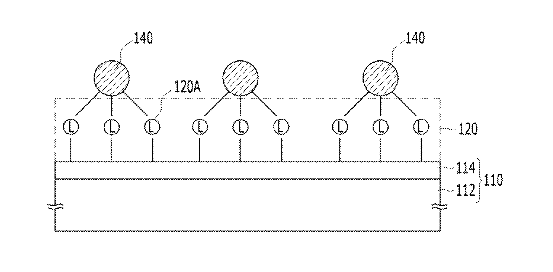
The patent is about a sensor that uses a flexible nanostructure made through a simple fabrication process. This process can control the size of nanoparticles, resulting in sensors that can operate stably, reproducibly, and reliably even when scaled. The technical effect of this patent is the creation of a flexible nanostructure sensor that can be mass-produced with control over nanoparticle size, resulting in stable and reliable operation of the application device.

Problems solved by technology

However, since the process is complicated, there is limited ability to apply the technology in mass-production.

Method used


Image

  • Sensor including flexible nanostructure and method for fabricating the same
  • Sensor including flexible nanostructure and method for fabricating the same
  • Sensor including flexible nanostructure and method for fabricating the same

Examples


first embodiment

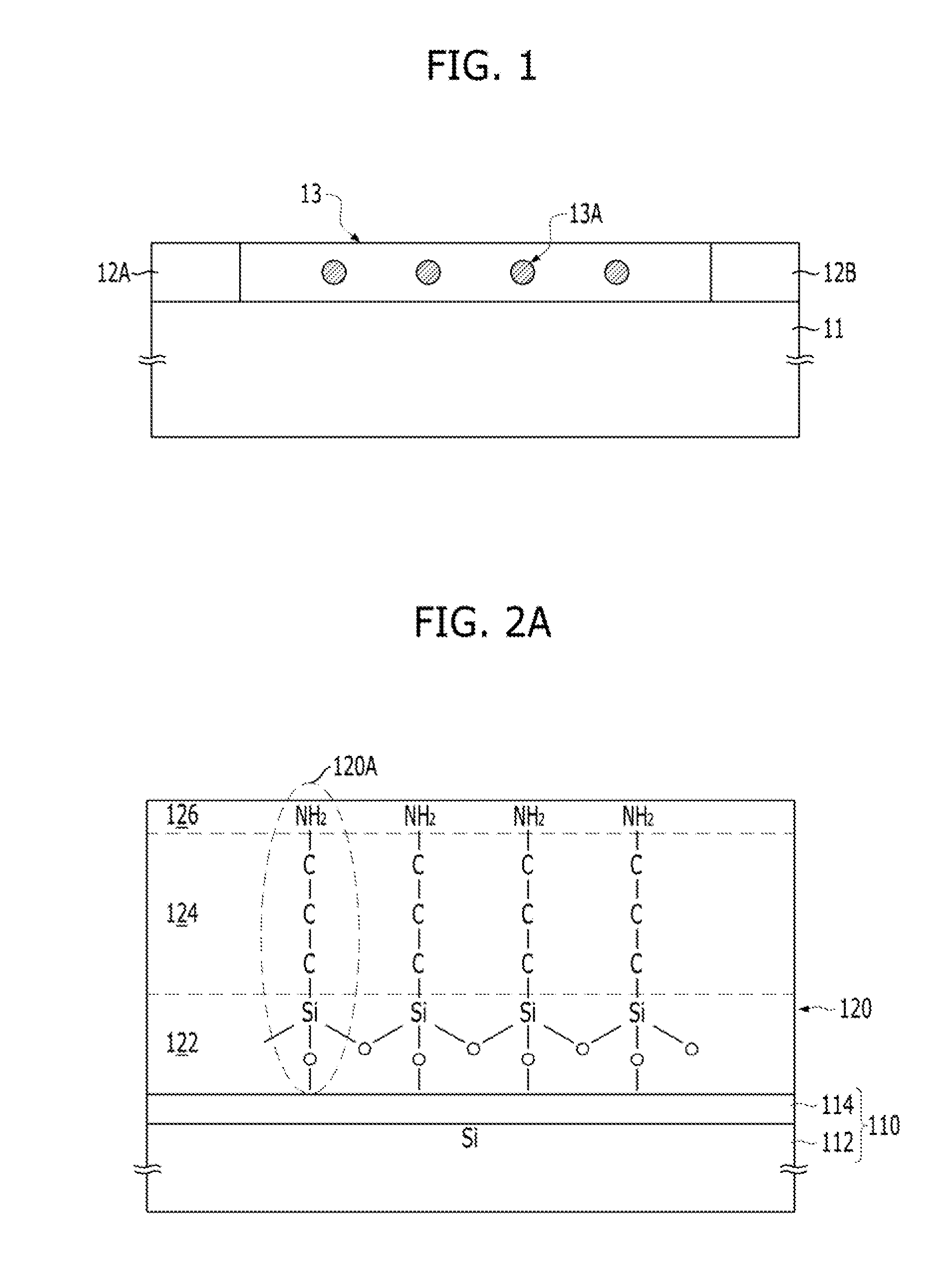
[0049]FIG. 1 is a cross-sectional view showing a portion of a sensor platform in accordance with a

[0050]Referring to FIG. 1, an anode 12A and a cathode 12B are formed over a substrate 11 to confront each other. Also, a nanostructure 13 is formed over the substrate 11. The shape and material of the substrate 11 may be different according to the application field. The nanostructure 13 may include metallic nanoparticles 13A of a single layer (one nanoparticle in thickness) or multiple layers (multiple nanoparticles in thickness).

[0051]FIG. 1 shows a portion of a sensor that is an embodiment. However, the technology of the present disclosure may be applied to diverse three-dimensional structures and the position and shape of the nanostructure 13 may be different to suit the applied platform. The present invention may be applied whenever a sensor having metallic nanoparticles is used to sense a marker. A marker is a target material and examples include enzymes, viruses, gases, and heavy ...

second embodiment

[0136]Nanostructure and Fabrication Method Thereof in Accordance with the Present Invention

[0137]FIGS. 3A to 3D are cross-sectional views illustrating a method for fabricating a sensor platform in accordance with a second embodiment. This embodiment also focuses on the fabrication of a nanostructure that is a sensing element of a sensor.

[0138]The method for fabricating the sensor platform in accordance with the second embodiment may include forming dielectric material particle supporters 222 on the surface where the linkers 224 are bonded (see FIG. 3A), bonding metal ions 230 to the linkers 224 (see FIG. 3B), and forming metallic nanoparticles 240 out of the metal ions 230 by applying energy (see FIG. 3C). The method may further include bonding receptors 250 to the surface of the metallic nanoparticles 240. Also, the method may further include supplying an organic surfactant of one or more kinds before or during the application of energy.

[0139]FIG. 3A shows the dielectric material p...


PUM

PropertyMeasurementUnit
Particle diameteraaaaaaaaaa
Flexibilityaaaaaaaaaa

Abstract

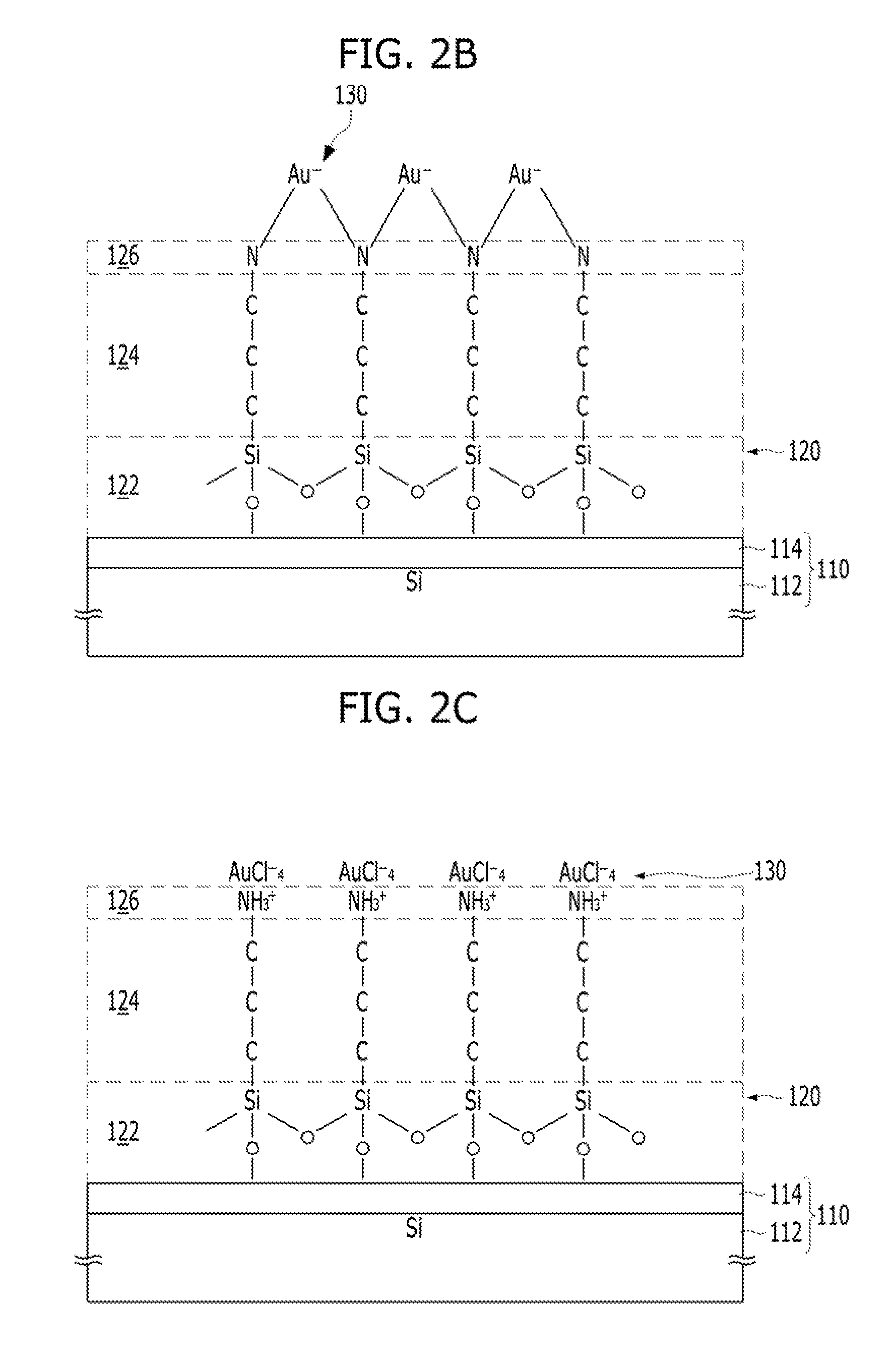
Provided is a sensor having a flexible nanostructure as a sensing element and a fabrication method thereof. The sensor includes a nanostructure as a sensing element for sensing a marker over a flexible substrate, wherein the nanostructure includes: a linker layer including linkers bonded to the flexible substrate; and metallic nanoparticles formed by the metal ions.

Description

CROSS-REFERENCE TO RELATED APPLICATIONS[0001]The present application claims priority of Korean Patent Application No. 10-2013-0159751, filed on Dec. 19, 2013, which is incorporated herein by reference in its entirety.BACKGROUND[0002]1. Field[0003]Various embodiments of the present disclosure relate to a sensor having a flexible nanostructure as a sensing element, and a fabrication method thereof.[0004]2. Description of the Related Art[0005]Nanostructures are widely used for sensors that sense light, enzymes, viruses, gases, and heavy metals by ligandizing a metallic nanoparticle.[0006]Particularly, in nanoparticles made of gold, a noble metal, Surface Plasmon Resonance (SPR) phenomenon occurs. The SPR phenomenon occurs when a collective oscillation of electrons is stimulated by incident light. Gold nanoparticles have desirable physical, chemical, and optical properties to support this phenomenon and its applications.[0007]For example, a biosensor may include a nanostructure for elec...

Claims


Application Information

Patent Timeline
IPC IPC(8): G01N21/552B32B38/00B32B37/24
CPCG01N21/554B32B37/24B32B2037/243B82Y35/00Y10S977/88B32B38/0008Y10T156/10B82B3/00G01N21/00G01N33/53
Inventor KIM, JUN-HYUNG
Owner SK INNOVATION CO LTD
Learn More