Fuel Cell Flow Channels and Flow Fields

a flow channel and fuel cell technology, applied in the field of fuel cells, can solve the problems of reduced performance, depletion of oxygen content in the air stream, and drop in air pressure, and achieve the effect of uniform current density

Active Publication Date: 2015-06-25
LOOP ENERGY INC
View PDF9 Cites 26 Cited by
  • Summary
  • Abstract
  • Description
  • Claims
  • Application Information

AI Technical Summary

Benefits of technology

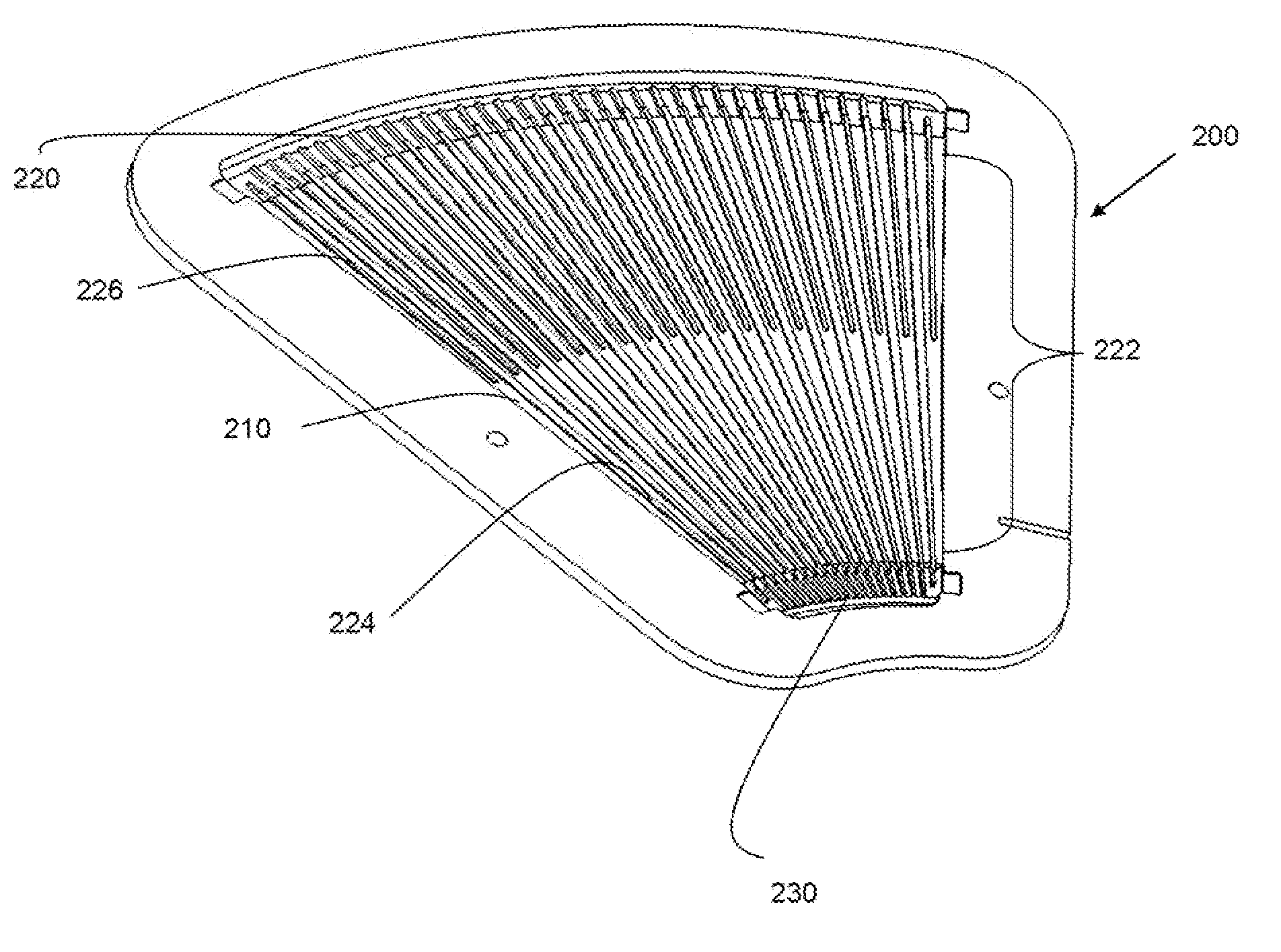
[0020]The above and other benefits are also achieved by a method of operating a fuel cell to produce electric power, in which the fuel cell comprises a membrane electrode assembly interposed between a first separator plate and a second separator plate, the membrane electrode assembly comprising an anode, a cathode, and a proton exchange membrane interposed between the anode and the cathode. The method comprises connecting the fuel cell to an electrical load; directing a fuel stream across the anode via at least one anode flow channel formed in a major surface of the first separator plate, wherein the at least one anode flow channel has a cross-sectional area that decreases along its length in the fuel flow direction; and directing an oxidant stream across the cathode via at least one cathode flow channel formed in a major surface of the second separator plate. The fuel stream is supplied to the at least one anode flow channel at a fuel stoichiometry such that there is substantially uniform current density across the fuel cell.
[0021]The above and other benefits

Problems solved by technology

As the air flows along the cathode flow channel(s), the oxygen content in the air stream tends to be depleted and the air pressure tends to drop.
This can result in reduced performance and uneven current density in the fuel cell.
There are a number of factors that can lead to irreversible performance losses and/or loss of electrochemical surface area during prolonged operation in PEM fuel cells.
The losses are mainly the result of catalyst layer degradation including platinum metal dissolution and corrosion of carbon supports.
Carbon corrosion can be caused by cell reversal which, in turn, can be a result of uneven reactant distribution and/or fuel starvation in regions of the anode.
Individually or coupled together, these degradation rates can be significant and require mitigation for long term stable operation.
Operating a fuel cell with uniform current density can reduce carbon corrosion and platinum dissolution, both of which are detrimental to fuel cell performance, longevity and durability.
The flow field channels described in the '169 patent w

Method used


Image

  • Fuel Cell Flow Channels and Flow Fields
  • Fuel Cell Flow Channels and Flow Fields
  • Fuel Cell Flow Channels and Flow Fields

Examples


Embodiment Construction

)

Anode Flow Channels—for Fuel Cell Operation on Pure or Dilute Fuel

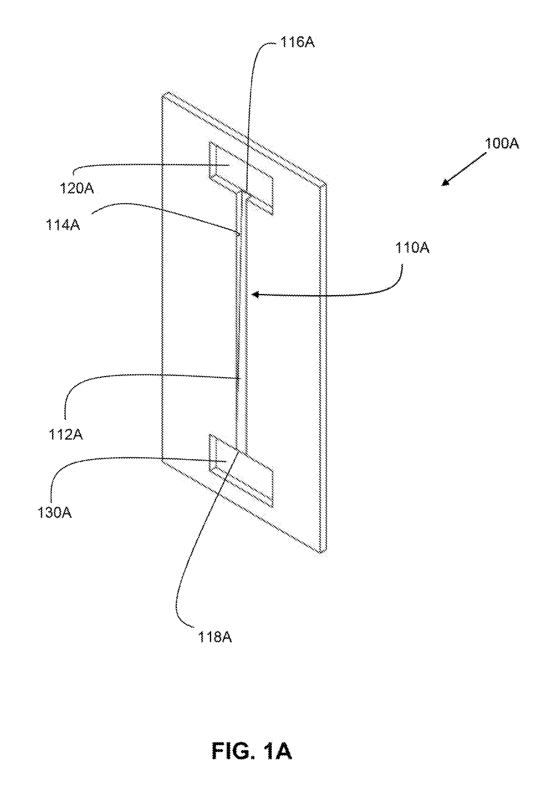
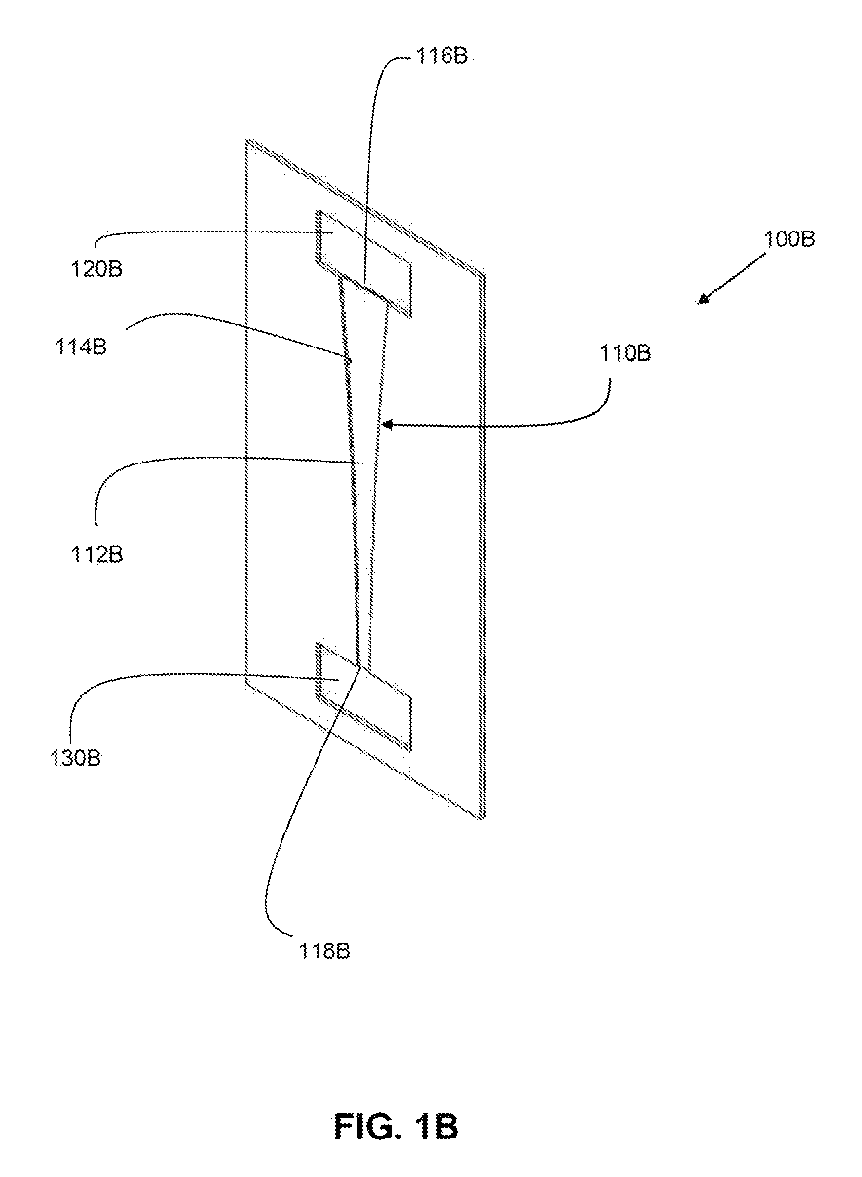
[0059]According to one embodiment, an anode flow field channel for a PEM fuel cell is designed for maintaining substantially constant fuel availability for the fuel cell electrochemical reaction along at least a portion of the length of the channel, for a given channel length and fuel stoichiometry, when the fuel cell is operating on either a pure or a dilute fuel stream.

[0060]We theorize that fuel availability is proportionate to fuel cell performance, and that uniform fuel availability promotes uniform current density, which is desirable for efficient fuel cell operation and improved performance. In the equations and description below, the fuel referred to is hydrogen, although the description would be applicable to other fuels such as methanol (although the value of the constant would change).

[0061]Hydrogen availability is a function of hydrogen mass flow and velocity, and is defined as follows:

AVAILH2(x)=m.H2(x)v...


PUM


Abstract

A fuel cell anode flow field includes at least one flow channel with a cross-sectional area that varies along at least a portion of its length. In some embodiments, the channel width decreases along at least a portion of the channel length according to a natural exponential function. This type of anode flow field can improve performance, reduce fuel consumption and/or reduce detrimental effects such as carbon corrosion and catalyst degradation, thereby improving fuel cell longevity and durability. When operating the fuel cell on either a substantially pure or a dilute fuel stream, this type of anode flow field can provide more uniform current density. These flow channels can be incorporated into reactant flow field plates, fuel cells and fuel cell stacks.

Description

CROSS-REFERENCE TO RELATED APPLICATIONS[0001]This application is a continuation of International Application No. PCT / CA2013 / 050627 having a filing date of Aug. 14, 2013 entitled “Fuel Cell Flow Channels and Flow Fields”, which is related to and claim priority benefits from U.S. Provisional Patent Application Ser. No. 61 / 683,156 filed Aug. 14, 2012, entitled “Fuel Cell Components, Stacks and Systems Based on a Cylindrical Fuel Cell Stack Architecture”, U.S. Provisional Patent Application Ser. No. 61 / 712,010 filed Oct. 10, 2012, entitled “Fuel Cell Anode Flow Field” and U.S. Provisional Patent Application Ser. No. 61 / 712,236 filed Oct. 10, 2012 entitled “Fuel Cell Flow Fields Incorporating Improved Flow Channels for Enhanced Performance”. This application also claims priority benefits from the '156, '236, and '010 applications.[0002]The PCT / CA2013 / 050627 international application, 61 / 683,156 provisional application, 61 / 712,010 provisional application, and 61 / 712,236 provisional applic...

Claims


Application Information

Patent Timeline
IPC IPC(8): H01M8/02H01M8/24H01M8/10
CPCH01M8/026H01M2008/1095H01M8/2465H01M8/10H01M8/0265H01M8/1011Y02E60/50
Inventor LEGER, DAVID E.MONTIE, GREG J.
Owner LOOP ENERGY INC
Why Eureka
Try Eureka