Optical isolator

a technology of optical isolators and isolators, which is applied in the field of optical isolators, can solve the problems of inability to meet the needs of the user, the dimension of the optical isolator becomes bulky, and enters an unstable state, so as to reduce the loss of absorption, expand the freedom of spatial dimensioning, and reduce the effect of optical isolator siz

Inactive Publication Date: 2015-07-02
SHIN ETSU CHEM IND CO LTD
View PDF3 Cites 2 Cited by
  • Summary
  • Abstract
  • Description
  • Claims
  • Application Information

AI Technical Summary

Benefits of technology

[0017]According to the present invention, it is possible to further downsize the optical isolator by merely using an easy-to-make hollow magnet unit, so that it becomes possible to expand the freedom in spatial dimensioning within the laser equipment in which the inventive optical isolator is incorporated. Also, the length of the Faraday rotator is about a half of that of the conventional TGG Faraday rotator, so that the absorption loss can be decreased and, as a result, the insertion loss, which is an important aspect of the optical isolator, is also decreased.

Problems solved by technology

This semiconductor laser has a characteristic of having a narrow emission spectrum and thus has an excellent conversion efficiency; on the other hand, a problem with this semiconductor laser is that it is so sensitive to the reflection return light that, when hit by a return light reflecting from an optical fiber joint interface or an object being measured, it enters in an unstable state.
Heretofore, iron-containing garnet (YIG), which is used in an optical isolator for communication, has been studied to make from it a Faraday rotator for 980-nm wavelength; however absorption of the iron (Fe), which is one of its components, increases in the range of wavelengths of 1 micrometer or shorter, and especially a loss of 1 dB or greater takes place at 980 nm, so that it has come to be considered not a good choice as the material to make a Faraday rotator.
As a consequence of this, a problem arises that the dimension of the optical isolator becomes bulky owing to the size of the magnet used.
Furthermore, it is so arranged that the magnetic field polarity of the second hollow magnet is opposite to that of the third hollow magnet with respect to a direction normal to the optical axis, and with such an arrangement of the magnet units, there occurs a limit to further downsizing of the optical isolator and the manufacturing operation can become complicated under the circumstances of the current trend of using a semiconductor laser for a 980-micrometer wavelength band, which is shorter than the wavelength of 1 micrometer.

Method used


Image

  • Optical isolator
  • Optical isolator
  • Optical isolator

Examples


example 1

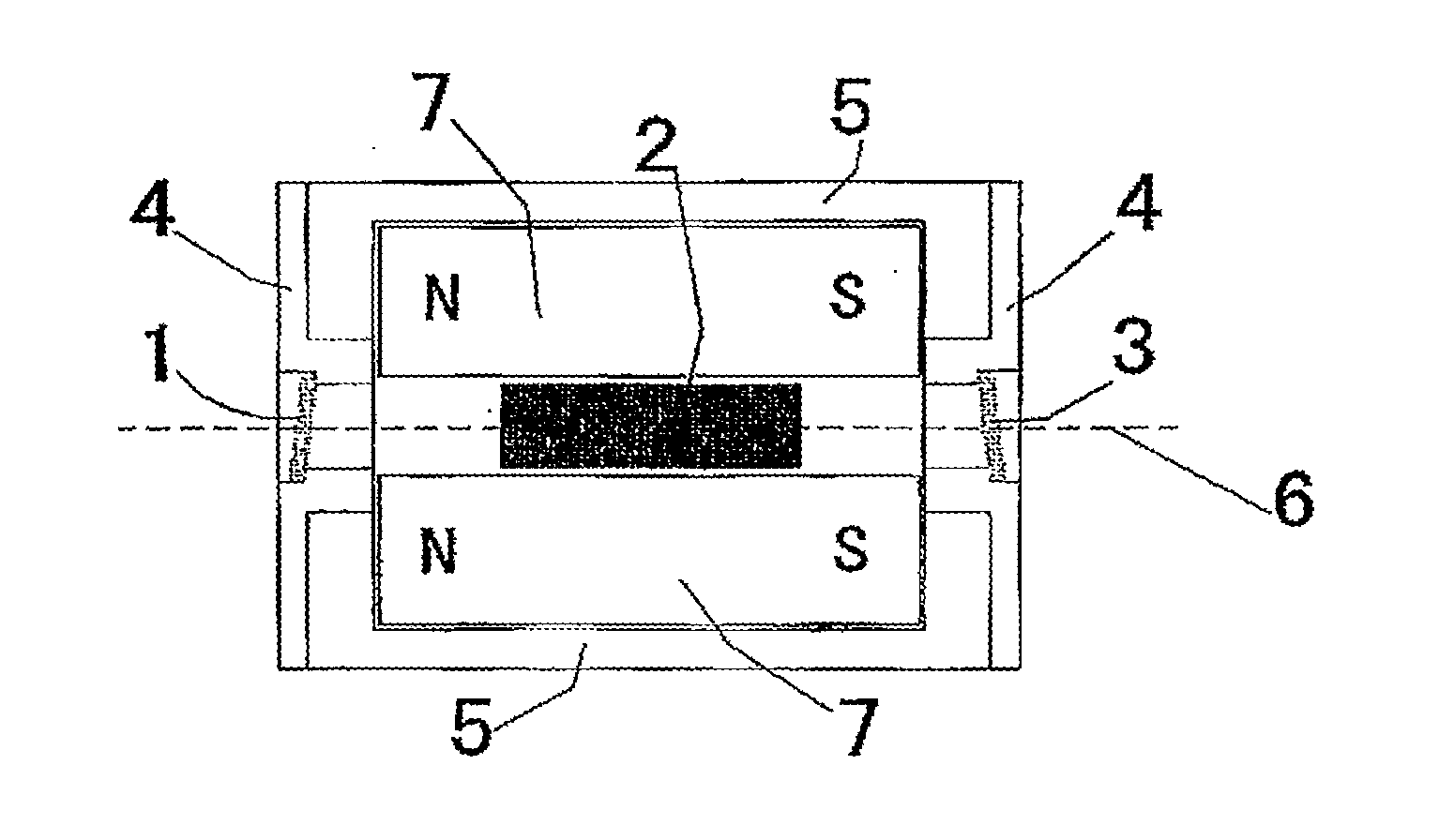
[0042]In Example 1, an optical isolator of 980 nm band having a structure as shown in FIG. 1 was made. An absorption type glass polarizer having a high transparency and a high extinction ratio in the 980 nm band was used to make an input polarizer 1 and an output polarizer 3, and an antireflective film having a central wavelength of 980 nm was adhered to the beam transmittance face, and in order to prevent the reflected beam from returning from the beam transmittance face to the incident beam path, metallic holders 5 are inserted by bonding them onto a polarizer holder 4, which has a tilt angle of 5 degrees, at the four corners of the bottom face of the polarizer.

[0043]Then, the Faraday rotator 2 was fixed in the middle of the hollow of the hollow magnet 7 after adjusting its position to where the magnetic field distribution created by the magnet becomes greatest. The input polarizer 1 and the output polarizer 3, which are arranged in this progressive order along the progressive pat...


PUM

PropertyMeasurementUnit
lengthaaaaaaaaaa
wavelengthaaaaaaaaaa
insertion lossaaaaaaaaaa

Abstract

An optical isolator for use with a wavelength band of 970-990 nm is improved in that it has a Faraday rotator made of an oxide material, which contains by 99% or more an oxide (TbxR1−x)2O3 where 0.5≦x≦1.0, and R is scandium, yttrium or any lanthanoid but Tb; the resulting Faraday rotator exhibits a Verdet constant of 0.30 min/Oe·cm or greater in the case of the wavelength band of 970-990 nm; and a hollow magnet is set to sheathe this Faraday rotator; and the sample length L is from 0.6 cm through 1.0 cm.

Description

[0001]The present non-provisional patent application claims priority, as per Paris Convention, from Japanese Patent Application No. 2013-271200 filed on 2013 Dec. 27, the disclosure of which is hereby incorporated by reference herein in its entirety.FIELD OF THE INVENTION[0002]The present invention relates to an optical isolator designed for use with wavelength bands of 970 nm-990 nm (herein merely referred to as “980 nm wavelength band”), which are employed in semiconductor lasers for optical measurement, optical sensing, and optical amplification.BACKGROUND TECHNOLOGY[0003]Conventionally, EDFA (erbium doped fiber amplifier) has been used for optical amplification of a 1.55-micrometer band communication laser, and a light source having a wavelength of 1480 nm or 980 nm is used as the excitation light source for this. The one with a wavelength of 980 nm has a higher amplification ratio than the one with a wavelength of 1480 nm, so that the former is increasingly adopted for practica...

Claims


Application Information

Patent Timeline
Patent Type & Authority Applications(United States)
IPC IPC(8): G02F1/09G02F1/00
CPCG02F1/093G02F1/0063G02F1/0036G02F1/0955
Inventor AKIRA, YAHAGISHINJI, MAKIKAWA
Owner SHIN ETSU CHEM IND CO LTD
Why Eureka
Try Eureka