Polyphase inductive power transfer system with individual control of phases

Active Publication Date: 2015-07-23
AUCKLAND UNISERVICES LTD
View PDF7 Cites 108 Cited by
  • Summary
  • Abstract
  • Description
  • Claims
  • Application Information

AI Technical Summary

Problems solved by technology

However, the optimal and efficient use of DG systems, especially in units based on wind and solar power, are largely affected by the stochastic nature of their energy production.
Consequently, large and expensive storage systems are required to alleviate such fluctuations and meet the demand in the most efficient way.
However, such prior art systems are incapable of energising individual primary (charging) pads/windings/coils/couplers, which are connected in series and powered by one primary supply, and magnetically coupled to pick-up pads (windings/coils) of multiple EVs, to allow for selective chargin

Method used


Image

  • Polyphase inductive power transfer system with individual control of phases
  • Polyphase inductive power transfer system with individual control of phases
  • Polyphase inductive power transfer system with individual control of phases

Examples


Example

FIRST EXAMPLE

A System to Control Multiple IPT Primary Windings

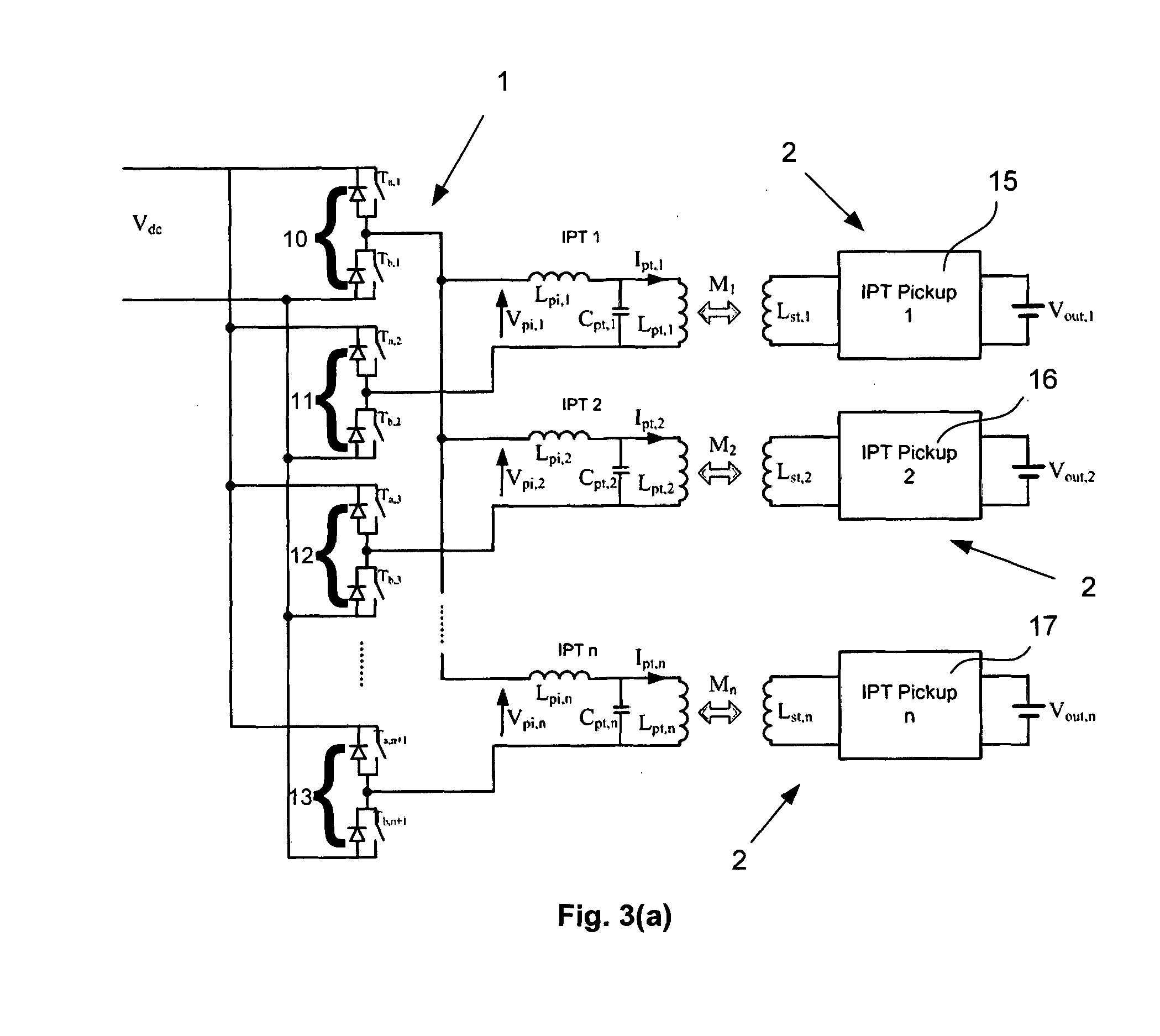
[0103]As a first example, FIGS. 3(a) and 3(b) show IPT systems according to two similar embodiments of the present invention. The IPT system shown in FIG. 3(a) consists of a primary power supply made from n+1 switch pairs in the form of half-bridge legs (referenced 10, 11, 12 . . . n) and n primary windings (Lpt,1-Lpt,n) which are each compensated using LCL compensation networks (comprising inductors Lpi,1-Lpt,n, capacitors Cpt,1-Cpt,n, and the primary windings Lpt,1-Lpt,n). Each of these primary windings can be magnetically coupled with a single pick-up 2 each having a single pick-up winding (Lst,1-Lst,n). Each of the pick-up windings, in this example, is controlled by its own controller (15-17), which can either be a bi-directional or a uni-directional controller, and supplies power to its own load. For convenience, no specific load is shown. Instead, the load is represented by a DC supply (Vout,1-Vout,n). The first leg...

Example

SECOND EXAMPLE

Polyphase Primary and Secondary

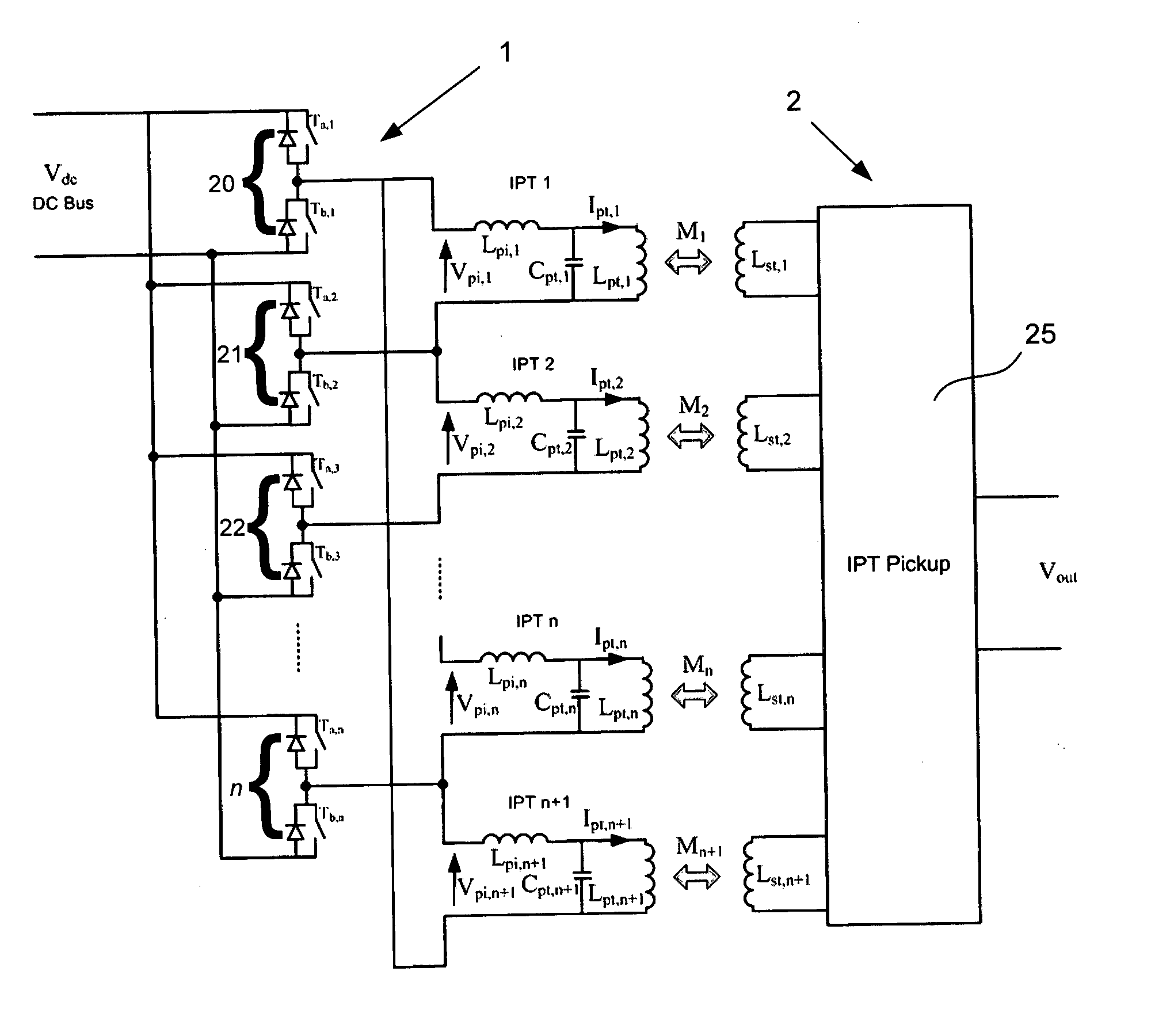
[0109]As a second example, a multiple winding primary may alternatively be coupled to a pick-up having multiple pick-up windings as shown in FIG. 4(a). FIG. 4(a) shows a system with multiple primary windings as described above with reference to FIG. 3(b). These are inductively coupled with a single pick-up having multiple pick-up windings (Lst,1-Lst,n+1), which are controlled by a single polyphase converter 25. Such a system may be used to charge a single vehicle such as a bus having multiple secondary or pick-up coils, for example. The present invention in such an application improves the power handling capacity of the IPT system, while minimizing losses. The n primary windings are powered using n half-bridge legs in the primary converter, which are operated in an interleaved fashion as described above with reference to FIG. 3(b). The pick-up converter 25 can be identical to the primary converter. Alternatively, the primary and / or pick-u...

Example

THIRD EXAMPLE

Three-Phase Bi-Directional IPT System

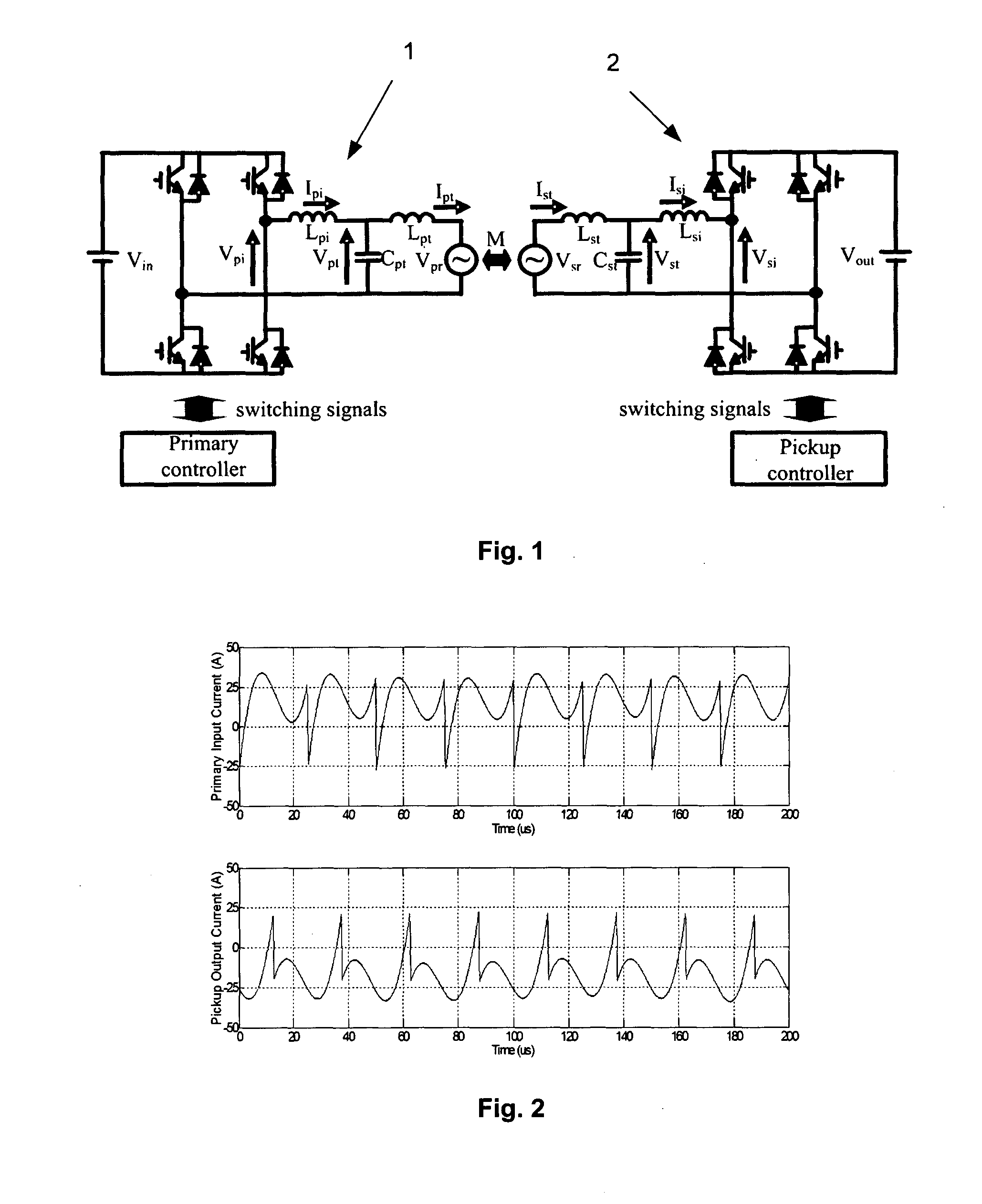
[0112]As a third example, a mathematical analysis together with simulation results of a three-phase IPT system with a single three-phase pick-up are presented to show that both the magnitude and direction of power flow can simply be controlled through either relative phase or magnitude modulation of the voltages generated by the three-phase converters. The performance of the proposed three-phase IPT system is compared with a conventional single-phase IPT system, and results show that the present invention is superior in performance and is particularly attractive for contactless, bi-directional and rapid charging / discharging applications. Although the example referred to in the description below relates to a three-phase IPT system, those skilled in the art will appreciate that the invention is generally applicable to polyphase IPT systems, i.e. systems having more than three-phases. Also, the system may be configured and / or used as ei...


PUM


Abstract

The present invention provides a polyphase inductive power transfer (IPT) system comprising a primary power supply comprising a plurality of primary conductors, the primary conductors being individually selectively operable to provide or receive a magnetic field for inductive power transfer; and at least one pick-up comprising one or more pick-up conductors, the one or more pick-up conductors each being individually selectively operable to magnetically couple with a primary conductor to control power transfer between the primary power supply and a load coupled or coupleable with the respective pick-up. The polyphase primary power supply may be used to power a plurality of single-phase pick-ups, one or more polyphase pick-ups, or a combination thereof. Also disclosed are polyphase primary and secondary converters for use in such a system.

Description

FIELD OF THE INVENTION[0001]This invention relates to both uni- and bi-directional Inductive Power Transfer (IPT) systems, and in particular IPT systems with a polyphase windings on either or both of the primary and secondary sides.BACKGROUND[0002]At present, consumer demands are focused more on safety, reliability, convenience, efficiency and state of the art of technology and not solely on the cost. Consequently, many new technologies are being implemented to meet such attributes of various applications. Green products or electronics can be considered as an ideal example, and they are intended to curtail the adverse effects of carbon footprint, over use of fossil fuels and associated environmental pollution, etc.[0003]Within a very short time period, many green energy regulations have been introduced and billions of dollars have been invested worldwide in green energy related research and development projects in search for efficient, cost-effective, and reliable green technologies...

Claims


Application Information

Patent Timeline
IPC IPC(8): H02J5/00H02J7/02
CPCH02J7/025H02J5/005B60L53/12B60L55/00H02J50/402Y02T10/7072Y02T90/14Y04S10/126H02J2310/48H02J50/12Y02E60/00Y02T10/70H02J50/005Y02T90/16H02J50/10Y02T90/12
Inventor MADAWALA, UDAYA KUMARATHRIMAWITHANA, DULEEPA JAYANATH
Owner AUCKLAND UNISERVICES LTD
Why Eureka
Try Eureka