Directional coupling communication apparatus
a communication apparatus and directional coupling technology, applied in the direction of cross-talk reduction, line-transmission details, high frequency circuit adaptations, etc., can solve the problems of increasing the speed of communication, hindering the miniaturization of the device, and affecting the transmission speed of the signal, so as to reduce reflection and improve the reliability of communication.
- Summary
- Abstract
- Description
- Claims
- Application Information
AI Technical Summary
Benefits of technology
Problems solved by technology
Method used
Image
Examples
example 1
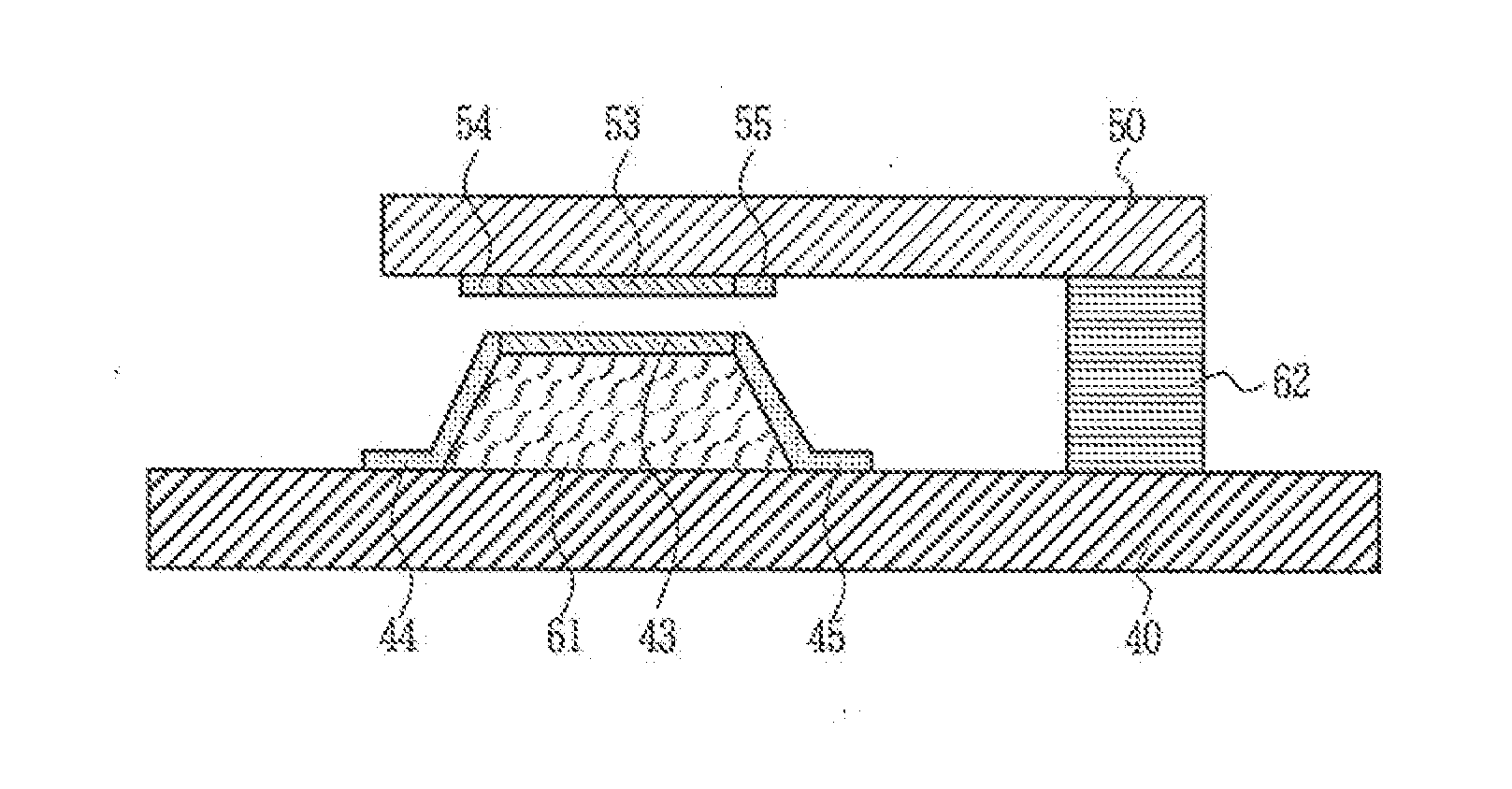
[0163]Next, the directional coupling differential communication apparatus according to Example 1 of the present invention is described in reference to FIGS. 7A to 9. FIGS. 7A and 7B are diagrams showing the structure of the directional coupling differential communication apparatus according to Example 1 of the present invention, where FIG. 7A is a schematic perspective diagram which illustrates an example of the interface realized between modules of the main substrate (motherboard) and a child substrate. For example, coupler components 411 and 412 using FPCs 421 and 422 are installed on the main substrate 40 in a mobile phone while coupler components 511 and 512 using FPCs 521 and 522 are installed on the rear surface of the display module (child substrate) 50.
[0164]The coupler components 411, 412, 511, and 512 are respectively provided with couplers 431, 432, 531, and 532, which are respectively connected to transmitter / receiver circuits 46 and 56 via lead transmission lines 441, 4...
example 2
[0173]FIGS. 11A and 11B are diagrams illustrating the directional coupling differential communication apparatus according to Example 2 of the present invention. Here, only the difference from Example 1 is described. FIG. 11A is a perspective diagram showing the terrace member and its surroundings, and FIG. 11B is a cross-sectional diagram showing the same as in FIG. 11A as viewed in the direction of the arrow. As shown in the figures, the portions of the lead transmission lines 44 and 45 of the coupler component 41 provided on the parent substrate side are made to run along the sides of the terrace member 61 in close proximity to the connection portions.
[0174]Meanwhile, the lead transmission lines 54 and 55 of the coupler component 51 on the child substrate side are in the same state as in FIGS. 7A and 7B, and therefore, the direction in which the lead transmission lines 44 and 45 run and the direction in which the lead transmission lines 54 and 55 run are different. Accordingly, th...
example 3
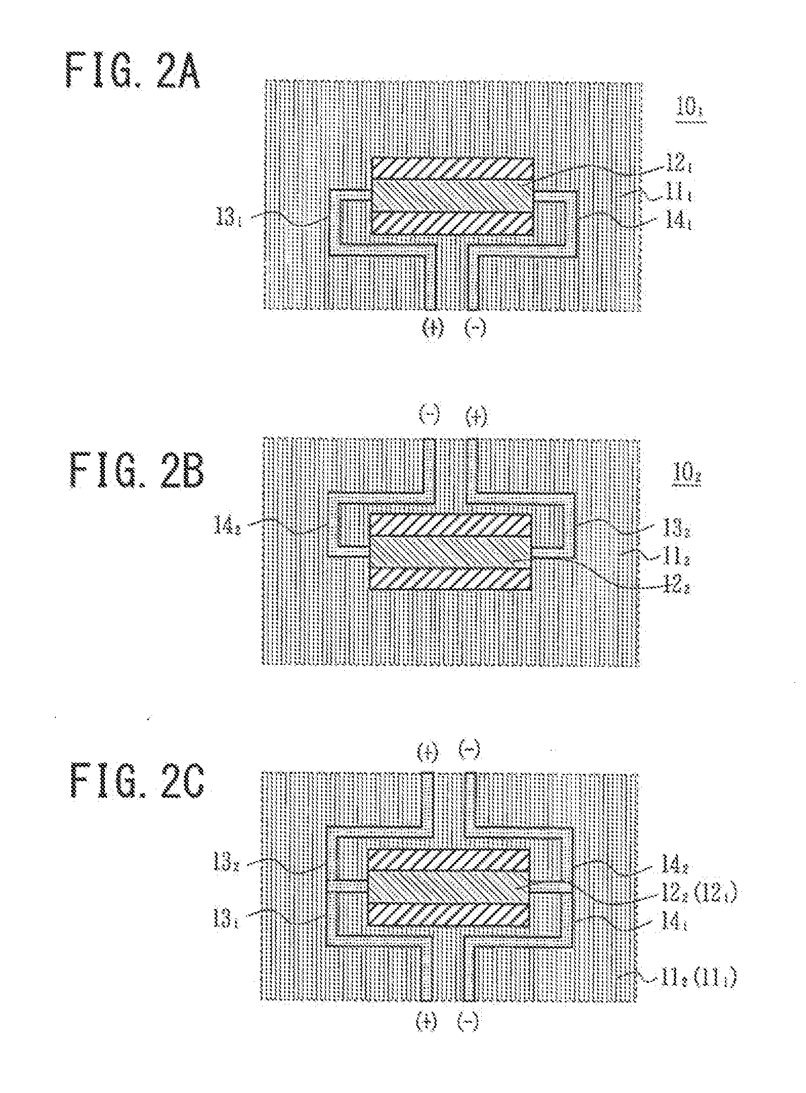
[0175]Next, the directional coupling differential communication apparatus according to Example 3 of the present invention is described in reference to FIGS. 12A to 12C. FIGS. 12A to 12C are diagrams illustrating the coupler components for forming the directional coupling differential communication apparatus according to Example 3 of the present invention, where FIG. 12A is a plan diagram showing a coupler component provided on the main substrate side, FIG. 12B is a plan diagram showing a coupler component provided on the child substrate side, and FIG. 12C is a perspective plan diagram showing a case where coupler components are layered on top of each other with the one on the child substrate side being inverted.
[0176]In Example 3, as shown in FIG. 12A or FIG. 12B, lead transmission lines 44, 45, 54, and 55 are connected to an end of a side of the couplers 43 and 53 along the long axis. This structure allows the lead transmission lines 44 and 45 to be completely prevented from overla...
PUM
 Abstract
Description
Claims
Application Information
 - R&D
- Intellectual Property
- Life Sciences
- Materials
- Tech Scout
- Unparalleled Data Quality
- Higher Quality Content
- 60% Fewer Hallucinations
Browse by: Latest US Patents, China's latest patents, Technical Efficacy Thesaurus, Application Domain, Technology Topic, Popular Technical Reports.
© 2025 PatSnap. All rights reserved.Legal|Privacy policy|Modern Slavery Act Transparency Statement|Sitemap|About US| Contact US: help@patsnap.com


