Optical Device And Methods

Active Publication Date: 2015-07-23
THOMAS SWAN & CO LTD
View PDF1 Cites 50 Cited by
  • Summary
  • Abstract
  • Description
  • Claims
  • Application Information

AI Technical Summary

Benefits of technology

The patent describes an improved method for reducing crosstalk in an optical switching device. The method involves selectively blocking at least one wavelength from an input port, passing other wavelengths on to a routing device and routing the other wavelengths. The routed light is then passed through intermediate optics to a spatial filter array. The spatial filter array passes the required diffraction orders and blocks the unwanted diffraction orders, creating significant suppression of the unwanted diffraction orders. This reduces crosstalk, facilitating 1×N switches with improved performance. The invention also provides a compound attenuation mechanism that reduces the number of routing holograms to be trained and uses a geometric method at the routing array to provide fine adjustment in attenuation levels. The spatial filter array suppresses crosstalk mechanisms and the optics uses crossed cylindrical components to take advantage of recent improvements in lens technology. Wavefront sensing may be implemented using the LCOS device to measure the dispersion equation for the assembled switch and reduce filter or channel calibration costs.

Problems solved by technology

LCOS defects can also cause crosstalk.
If the faulty pixel is positioned well away from the flyback region, this may not be a problem, but if the faulty pixel is in the middle of the flyback region the unwanted orders created by that region of the LCOS may increase Similarly a fault in the circuits used to update the pixel voltages in a particular row or column could increase crosstalk.
A faulty row will affect every channel, while a faulty column will affect every phase ramp applied to the same channel The effect of intolerance to such defects is to reduce LCOS yields, and therefore increase the yielded cost of the LCOS inside each WSS.
This of course further increases the number and cost of training and storing the routing and attenuation holograms.

Method used


Image

  • Optical Device And Methods
  • Optical Device And Methods
  • Optical Device And Methods

Examples


first embodiment

[0172]To illustrate the principles, an optical switch is shown in FIGS. 11-17.

[0173]FIG. 17 shows a highly-schematic equivalent optical circuit for the optical switch 6000, in order to clarify the differences with respect to the prior art. Referring to FIG. 17, an N×1 optical switch 6000 has N spatially separate input beams 1100 connected to input optics 1, and a single output beam 1106 delivered by output optics 1102. In one embodiment, each input beam 1100 is delivered from a respective individual optical fibre forming an input port, and the output 1106 is delivered into a single optical fibre forming an output port. One or more of the input beams may include an ensemble of different wavelengths.

[0174]Light passes from the input optics to a first array 1103, referred to herein as a spatial filter array, then via intermediate optics 1104 to a second array 1105, referred to herein as a routing array. From the routing array light passes to the output optics 1102.

[0175]From each of th...

second embodiment

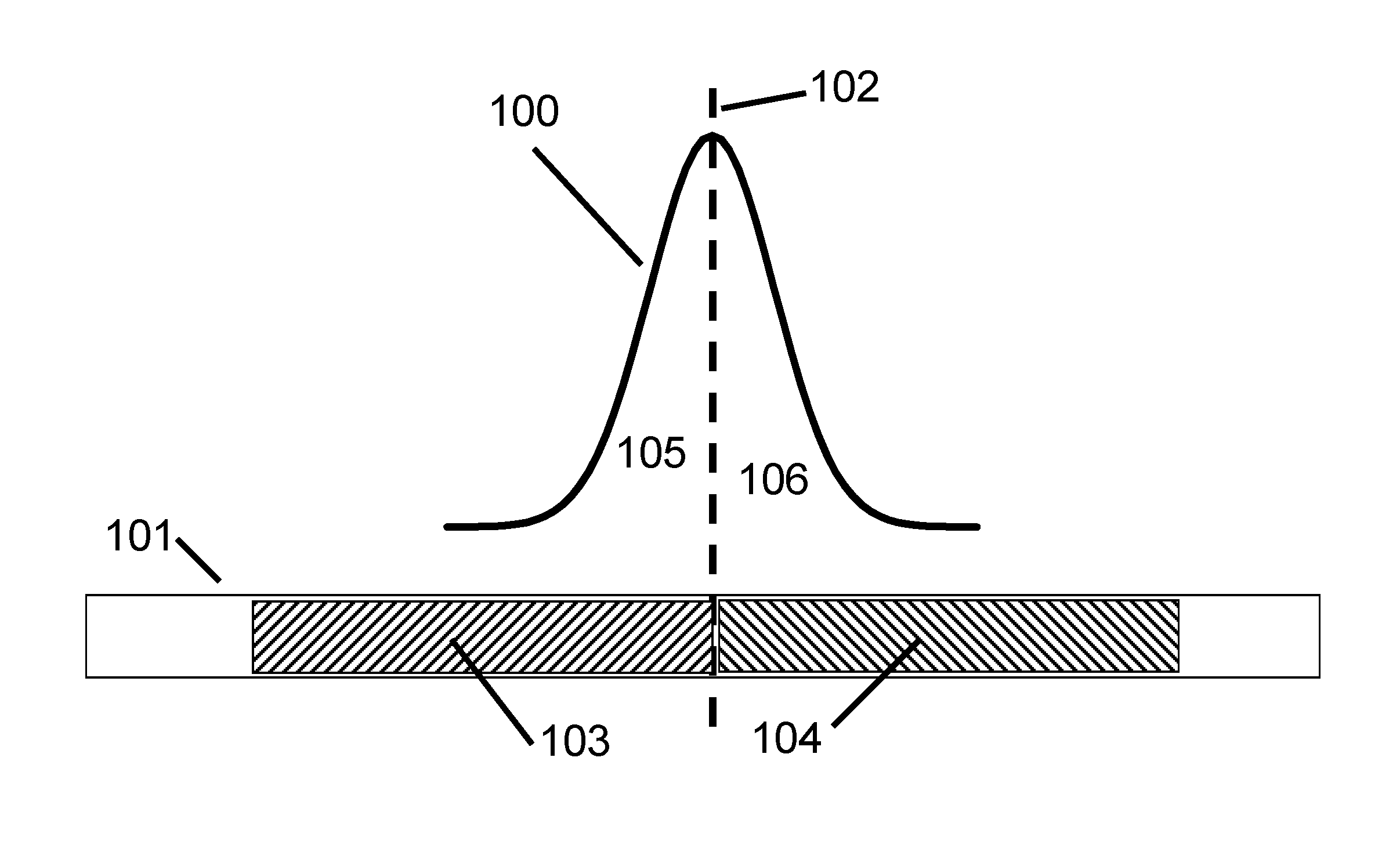
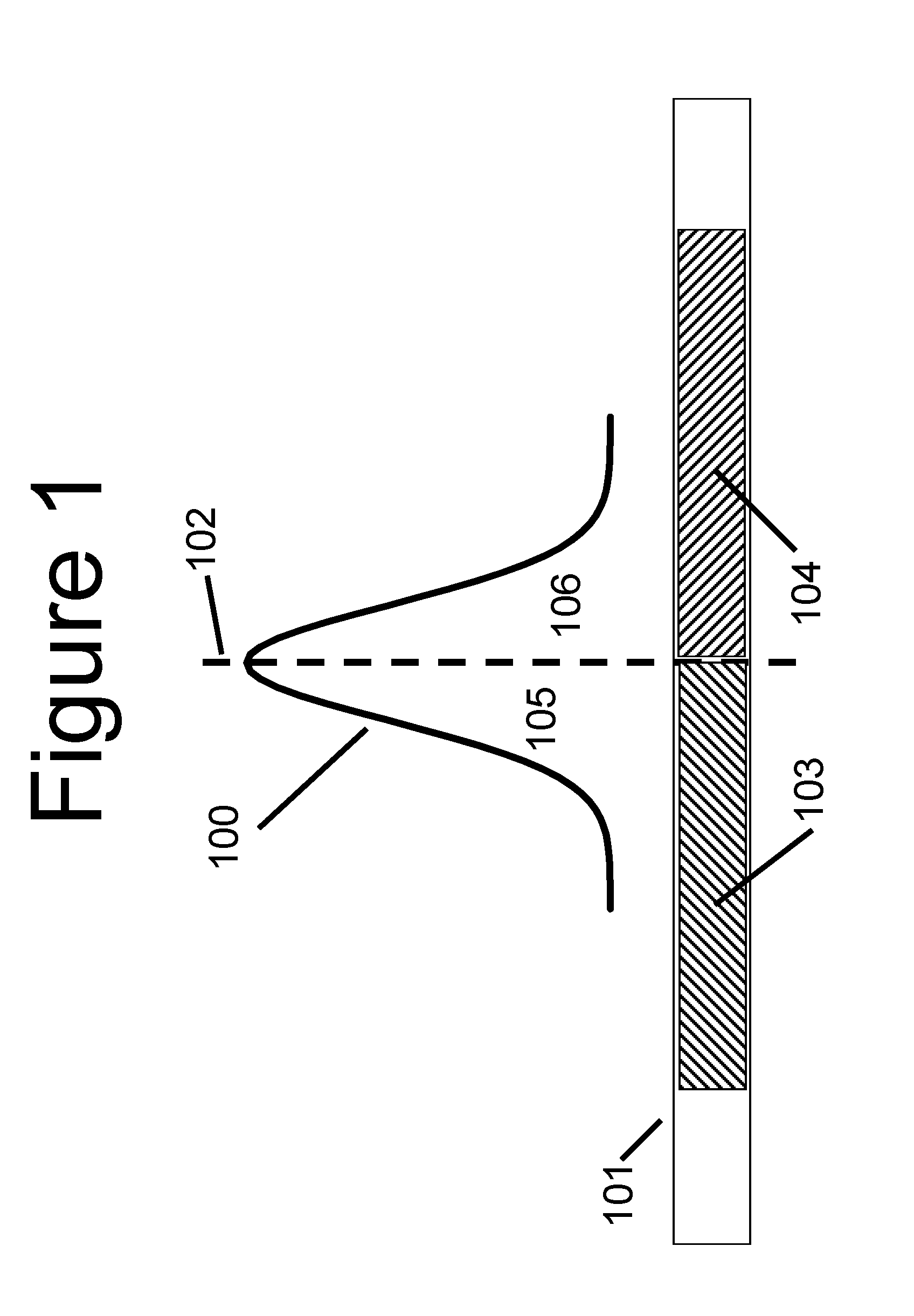
[0235]Referring to FIG. 4, in this second embodiment, the centre group of pixels 404 has a routing hologram applied, while the outer groups, 403 and 405, have uniform phase applied.

[0236]Whether we reject, or route, the centre portions, it is advantageous to divide the group into 3 (or more) subgroups, because it gives a finer resolution in the attenuation levels than a single group, as shown in FIG. 5. Also then the output beam can have, at least approximately, even symmetry, for example where an odd number of subgroups is provided. This even symmetry makes it reasonably resilient to positional tolerances in the output.

[0237]FIG. 6 shows a graph of attenuation for this second embodiment, to investigate the resolution in fine levels between 0 and 1.5 dB, again using a value for the spot radius measured in the switch plane direction (parallel to arrow 4002 in FIG. 40), of 750 μm. The graph in FIG. 6 shows the calculated transmittance, plotted vs. the position of the subdivision 409, ...

third embodiment

[0333]The third embodiment has a half wave plate 1410 disposed spaced in front of the first LCOS array 1103.

[0334]In variants of the second and third embodiments, the half-wave plate instead of being physically separate and spaced from the respective LCOS array, is deposited on the cover material of the LCOS, and windowed, that is limited to the area where it is required to rotate the polarisation of the incident light to and from that required for the liquid crystal layer to perform its required function.

[0335]If the spatial filter uses the liquid crystal layer in amplitude modulation mode, polarisation manipulation optics such as a polariser or polarising beam splitter are required at some point in the system, to reject and handle the blocked light, and to deliver light to the liquid crystal layer that is linearly polarised across the range of incident wavelengths.

[0336]In an embodiment the cover glass in front of the spatial filter array includes as well as a half wave plate, a p...


PUM


Abstract

A device and method for controlling light by wavelength in a device with a switch plane and a dispersion plane uses optics providing an imaging function in the dispersion plane, and a Fourier transform function in the switch plane, so as to enable crosstalk to be reduced

Description

1 FIELD[0001]The present disclosure concerns optical systems, device and methods. Some embodiments relate to optical switches, others to devices and methods of controlling light.2 BACKGROUND2.1 WSS Technology[0002]Wavelength selective switches—hereinafter “WSS”—are now an established component in WDM—wavelength division multiplexing—networks. The main technologies are MEMS, LC and 2D LCOS, the latter being a two dimensional array of pixels implemented in a Liquid Crystal on Silicon device.[0003]As in known to those skilled in the art, WDM requires plural wavelength channels. Each channel has a channel width or passband, i.e. the channel comprises more than one wavelength, usually a continuum of wavelengths. Channels are usually spaced apart by wavelength regions that do not or should not have light in them. Light does not necessarily mean visible light. As is well known, communications may use NIR.[0004]A consequence of WDM is the need to demultiplex, i.e. extract one or more wavele...

Claims


Application Information

Patent Timeline
IPC IPC(8): H04Q11/00
CPCH04Q11/0005H04Q2011/0009H04Q11/0003H04J14/02H04J14/0212G02B6/356G02F1/31G02B6/354
Inventor HOLMES, MELANIE
Owner THOMAS SWAN & CO LTD
Why Eureka
Try Eureka