Cutting tool and cutting method

a cutting tool and cutting method technology, applied in the field of cutting tools and cutting methods, can solve the problems of not being suited to hard brittle materials, and achieve the effects of preventing the occurrence of a factor inhibiting cutting work, reducing the need for excessive laser light heating, and improving the efficiency of laser light emission

Inactive Publication Date: 2015-08-06
ADAMANT IND +1
View PDF1 Cites 15 Cited by
  • Summary
  • Abstract
  • Description
  • Claims
  • Application Information

AI Technical Summary

Benefits of technology

[0033]According to the present invention, it is possible to cut a hard brittle material without generation of cracks, avoid total reflection of laser light, and improve the efficiency of emitting the laser light.
[0034]Further, it is possible to prevent the occurrence of a factor for inhibiting cutting work, which caused by cutting dust produced from the material to be cut during the cutting work. Thus, the material to be cut can be heated directly by irradiation of the laser light, and the need for excessive laser light heating can be eliminated. Therefore, it is possible to cut the hard brittle material with high dimensional accuracy.
[0035]Furthermore, according to the present invention, by propagating the laser light through the cutting tool, it is possible to uniform the direction of irradiation of the laser light and the direction of approach of the cutting tool toward the material to be cut. Therefore, it is possible to cut the material to be cut even if the material is a non-light-transmittable material. This allows fabrication of a three-dimensional structure having an internal shape such as a cylinder by cutting work.

Problems solved by technology

However, these cutting methods using laser light are addressed for glass materials, hard-to-cut metal materials, and the like, but are not suited for hard brittle materials.

Method used


Image

  • Cutting tool and cutting method
  • Cutting tool and cutting method
  • Cutting tool and cutting method

Examples


Embodiment Construction

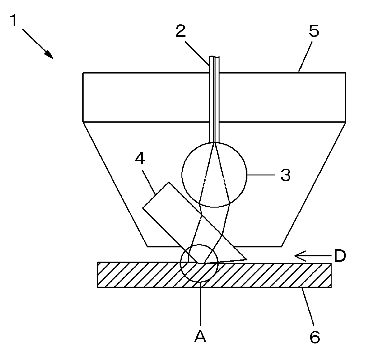
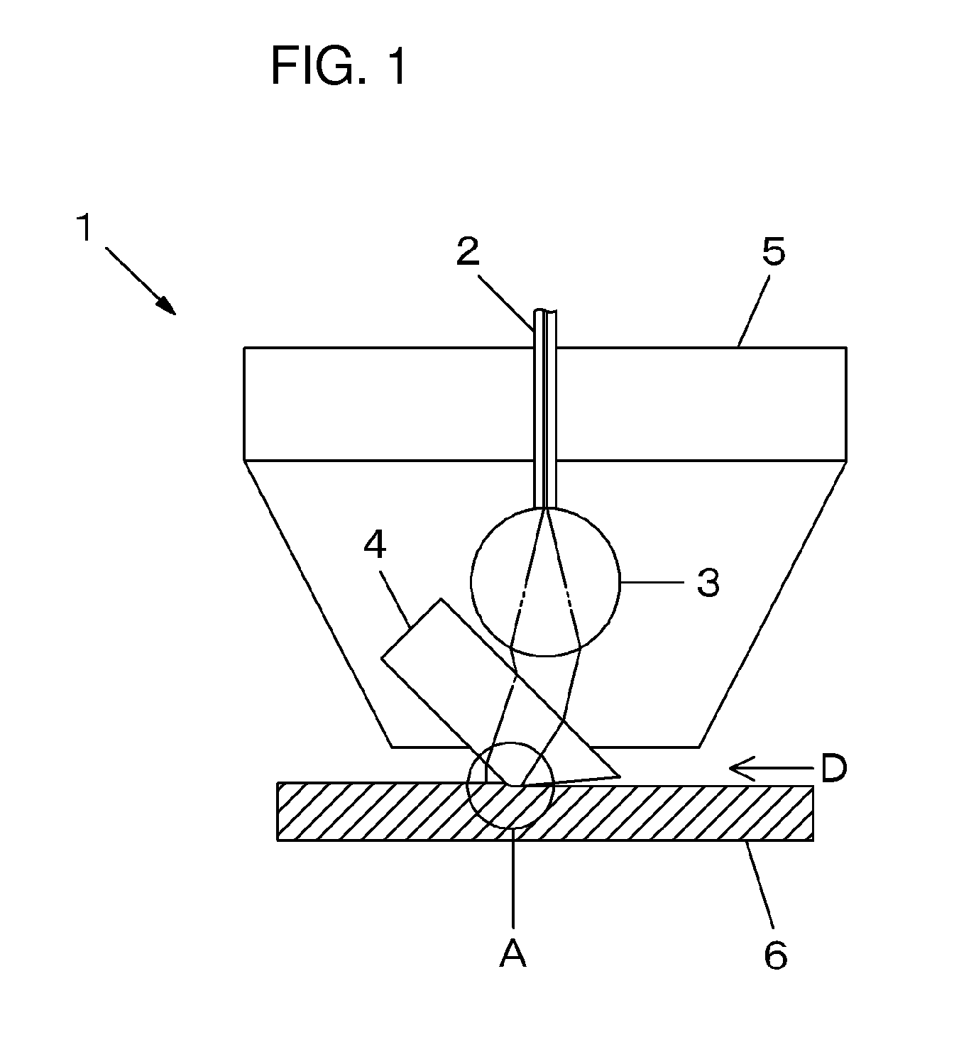
[0047]A cutting tool and a cutting method according to the present invention will be described below in detail. FIG. 1 is a schematic diagram for describing the cutting tool and the cutting method according to an example of an embodiment of the present invention. As illustrated in FIG. 1, a cutting apparatus 1 according to the embodiment includes an optical fiber 2, a convergence lens 3, a cutting tool 4, and a casing 5 supporting these components. A part of an end surface of the cutting tool 4 is brought into contact with a material to be cut 6, and the material to be cut 6 is cut at the contact part.

[0048]In addition, in the present invention, the cutting tool 4 is formed from a light-transmittable material through which laser light can pass. The laser light is propagated through the optical fiber 2. The laser light is converged on the convergence lens 3 and then propagated through the cutting tool 4. The laser light is then incident to the material to be cut 6 via the cutting too...


PUM

PropertyMeasurementUnit
cutting depthaaaaaaaaaa
cutting speedaaaaaaaaaa
distanceaaaaaaaaaa

Abstract

A cutting tool for cutting a hard brittle material is formed from a light-transmittable material through which laser light can pass and is provided with a rake angle, the laser light is propagated through the cutting tool, the cutting tool and the hard brittle material are brought into contact with each other, the laser light is incident to at least a contact part where the cutting tool and the hard brittle material are in contact with each other and a part with the rake angle, the laser light except for Fresnel reflection light on an end surface of the cutting tool is incident to the hard brittle material through the contact part and the rake angle part to soften the hard brittle material, and the softened hard brittle material is cut.

Description

TECHNICAL FIELD[0001]The present invention relates to a cutting tool and a cutting method, specifically to a cutting tool and a cutting method for use in cutting hard brittle materials.BACKGROUND ART[0002]Single crystals such as silicon carbide, sapphire, silicon (Si), and germanium (Ge), and ceramics such as alumina, zirconia, ferrite, and silicon nitride are hard brittle materials that cannot be cut but are processed by grinding or polishing work.[0003]There have been devised methods for grinding or polishing hard brittle materials with use of particles of diamond or cubic boron nitride (CBN). In addition, methods for cutting such materials through heating with laser light or the like have been also attempted. However, these cutting methods using laser light are addressed for glass materials, hard-to-cut metal materials, and the like, but are not suited for hard brittle materials. Nevertheless, with the advancement of laser techniques in recent years, there have been increasingly ...

Claims


Application Information

Patent Timeline
Patent Type & Authority Applications(United States)
IPC IPC(8): B23P25/00B23B27/20
CPCB23P25/006B23B27/20Y10T407/24
Inventor YAMASHIDA, HIRONORISUGIMURA, TERUMICHISUGIMURA, AKINORIHORIGUCHI, KOJIIMAIZUMI, NOBUO
Owner ADAMANT IND
Why Eureka
Try Eureka