Energy Storage System Preventing Self from Overheating and Method for Preventing Energy Storage System from Overheating

Inactive Publication Date: 2015-08-06
CHNA ENERGY INVESTMENT CORP LTD
View PDF6 Cites 7 Cited by
  • Summary
  • Abstract
  • Description
  • Claims
  • Application Information

AI Technical Summary

Benefits of technology

[0021]In the energy storage system for overheat prevention and the method for preventing overheat of the energy storage system according to the invention, because the terminal posts and/or the electrical connection elements of the energy storage system are in thermal connection with the heat transfer

Problems solved by technology

However, with recent development of smart grid and the increasing amount of interest in renewable energy (e.g. wind power, solar energy and so on), the demand in large-scale energy storage system has never been more imperative.
The emerging applications in technology pose new challenges to lead-acid batteries and other types of batteries.
For example, overheating occurs in almost any large-scale applications that are usually of high rate and multi-cycle, which shortens the cycle life and sometimes even causes permanent damage to the batteries and especially to the lead acid batteries.
But this, on the other hand, increases the total system cost tremendously.
The limited contact of the acid, separators and plates with the plastic case walls limits the heat transfer out of the cell because of the lack of a heat dissipation passage and therefore increases the operating temperature, which limits the cycle life of valve-regulated type lead-acid battery and thus their potential applications in large-scale.
In some instances thermal runaway can lead to softening or even burning of the polymer case.
The shell of a cell is general

Method used


Image

  • Energy Storage System Preventing Self from Overheating and Method for Preventing Energy Storage System from Overheating
  • Energy Storage System Preventing Self from Overheating and Method for Preventing Energy Storage System from Overheating
  • Energy Storage System Preventing Self from Overheating and Method for Preventing Energy Storage System from Overheating

Examples


Embodiment Construction

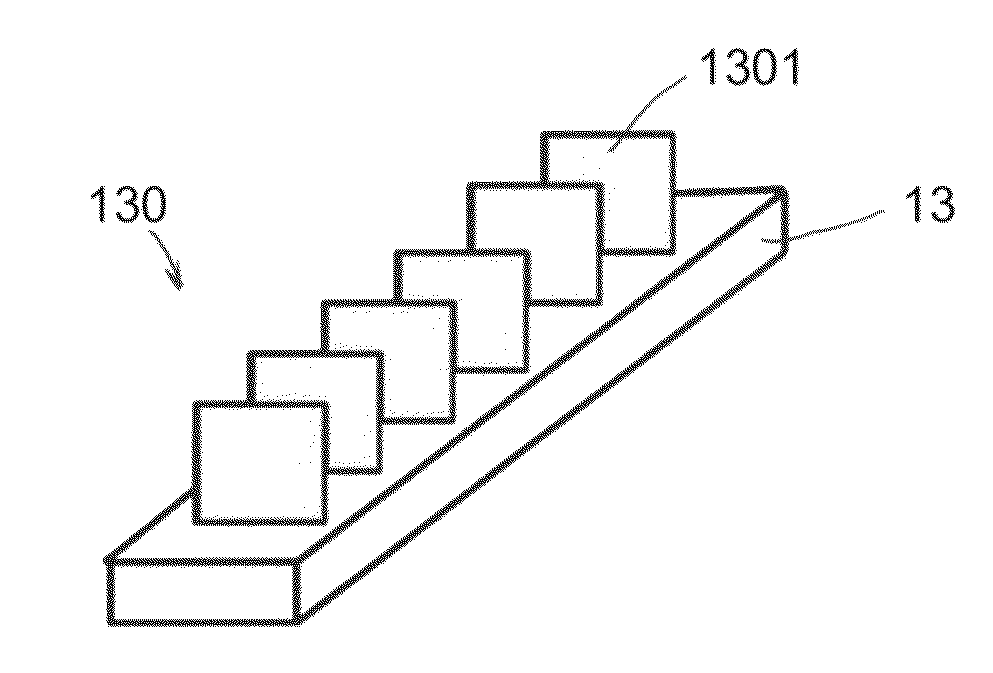
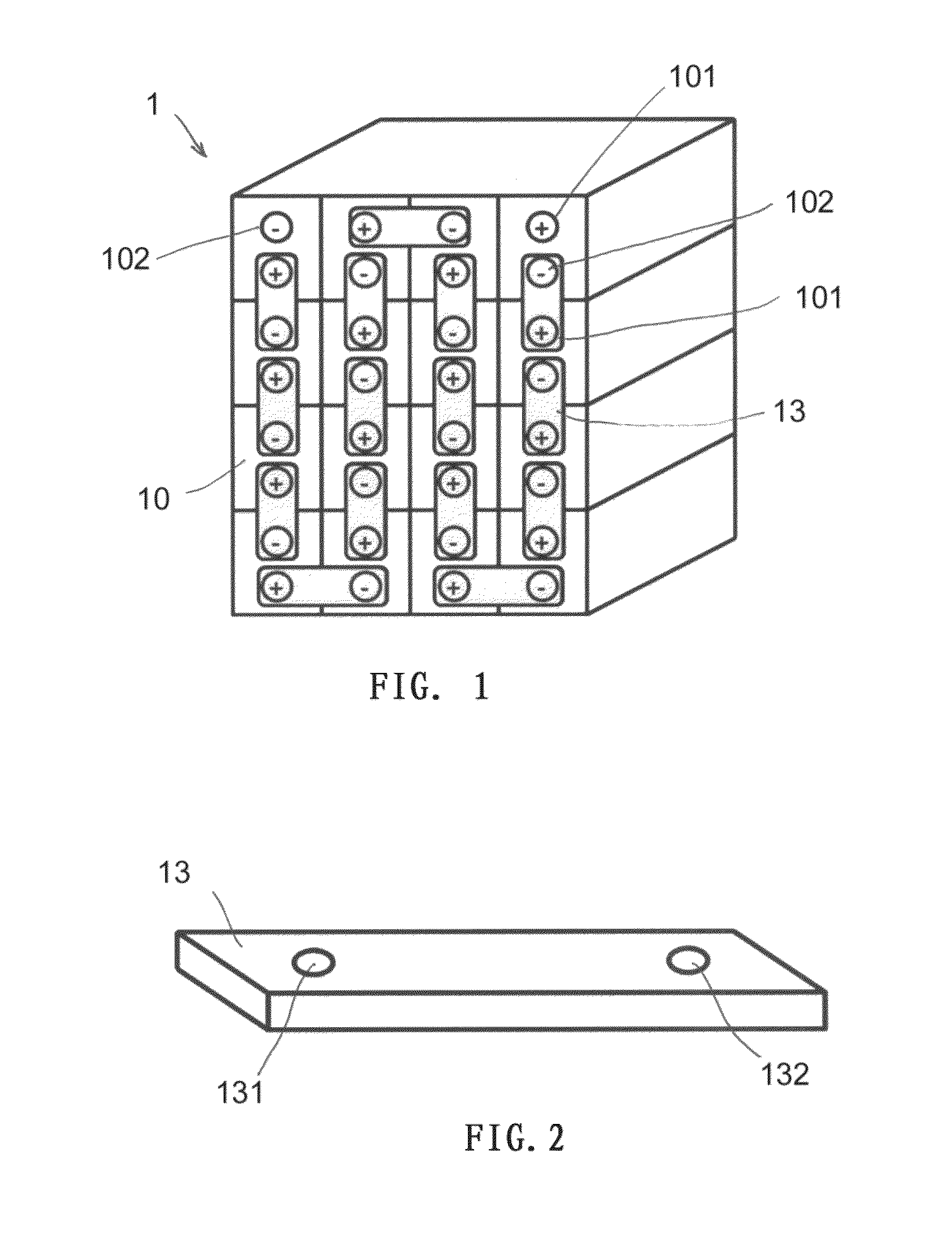
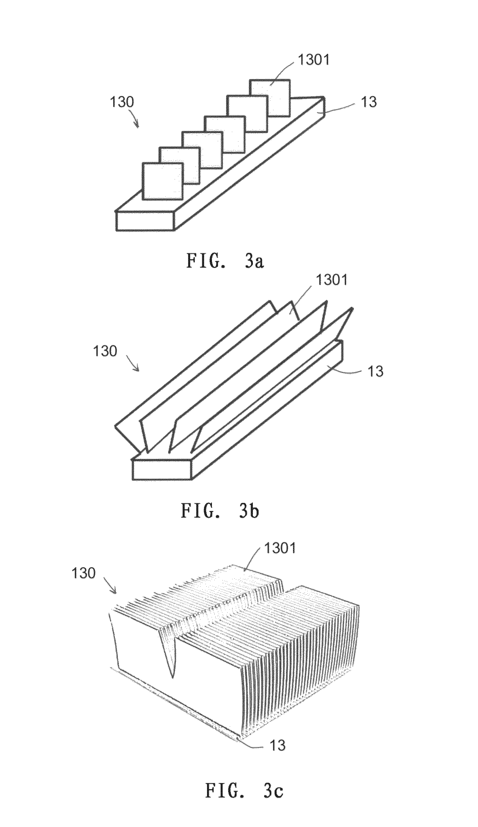
[0034]FIG. 1 shows an example of a prior art energy storage system (which is generally referred to as an electrical energy storage system). The energy storage system may be a battery system, a capacitor system or other electrical energy storage means. A battery system will be illustrated in detail below as an example. The battery system 1 includes a plurality of battery units (energy storage units) 10, having e.g. one or more cells (energy storage cells). The plurality of battery units 10 may be arranged in any array, and each has two terminal posts 101 (a positive terminal post) and 102 (a negative terminal post) leading from the interior thereof. An electrical connection between different battery units is achieved by means of an electrical connection strap (electrical connection element) 13 one end of which is connected to the positive terminal post 101 of one battery unit and the other end of which is connected to the negative terminal post 102 of another battery unit. The electr...


PUM

PropertyMeasurementUnit
Electrical conductoraaaaaaaaaa
Metallic bondaaaaaaaaaa

Abstract

The present invention provides an energy storage system, particularly a battery system, that is capable of preventing self from overheating, comprising at least one energy storage unit each having two terminal posts extending outwards from the interior thereof; when there are at least two energy storage units, electrical connection therebetween is achieved by electrical connection elements that bridge the terminal posts of different energy storage units; at least one of the terminal posts and/or the electrical connection elements is in thermal connection with a heat transfer surface enlarging structure made of solid heat conductive materials. The present invention further relates to a method for preventing overheat of an energy storage system.

Description

TECHNICAL FIELD[0001]The present invention relates to an energy storage system, particularly to a battery system, and more particularly to a valve-regulated type lead-acid battery system, that is capable of preventing self from overheating. The present invention further relates to a method for preventing overheat of the energy storage system.BACKGROUND OF THE INVENTION[0002]As an energy storage system, a battery and a system thereof are means for storing electric energy so as to restore the energy when needed. Typically, a cell includes two electrodes arranged in the electrolyte, i.e. an anode and a cathode. As known in related technologies, an electrical apparatus to be operated is usually connected across the cathode and anode at two ends to obtain electrical energy from the cell.[0003]Invented in 1859, the lead acid battery has more than 150 years of history. It still remains to be one of the most popular batteries nowadays and has been widely used in technical fields such as ele...

Claims


Application Information

Patent Timeline
IPC IPC(8): H01M10/6551H01M2/10H01M50/204H01M50/24H01M50/507
CPCH01M10/6553H01M10/6551H01M10/613H01M2/206H01M2/1022H01M2/1077H01M2/0292Y10T29/49108Y02E60/10H01M50/124H01M50/1245H01M50/204H01M50/507H01M50/24
Inventor JIN, HONGBRILMYER, GEORGE H.NISPEL, MICHAEL T.REN, DONGXUEBAI, DAJUN
Owner CHNA ENERGY INVESTMENT CORP LTD
Why Eureka
Try Eureka