Internal combustion engine

a combustion engine and combustion chamber technology, applied in the direction of exhaust treatment, combination devices, mechanical devices, etc., can solve the problems of exhaust gas heat content that is not sufficient to complete the urea-water solution treatment, exhaust gas system blockage, and conversion loss in the scr reaction

Active Publication Date: 2015-08-20
DEUTZ AG
View PDF13 Cites 18 Cited by
  • Summary
  • Abstract
  • Description
  • Claims
  • Application Information

AI Technical Summary

Benefits of technology

[0030]The fact that ammonia is metered in as the reducing agent instead of a urea-water solution eliminates the need for processing at the exhaust-gas temperature. A challenging aspect for me

Problems solved by technology

Particularly at low-load operating points, however, the amount of heat contained in the exhaust gas is often not sufficient to completely process the injected urea-water solution necessary for the complete reduction of the nitrogen oxides that are likewise present in the exhaust gas.
This results in deposits (crystallization) of

Method used


Image

  • Internal combustion engine
  • Internal combustion engine
  • Internal combustion engine

Examples


Embodiment Construction

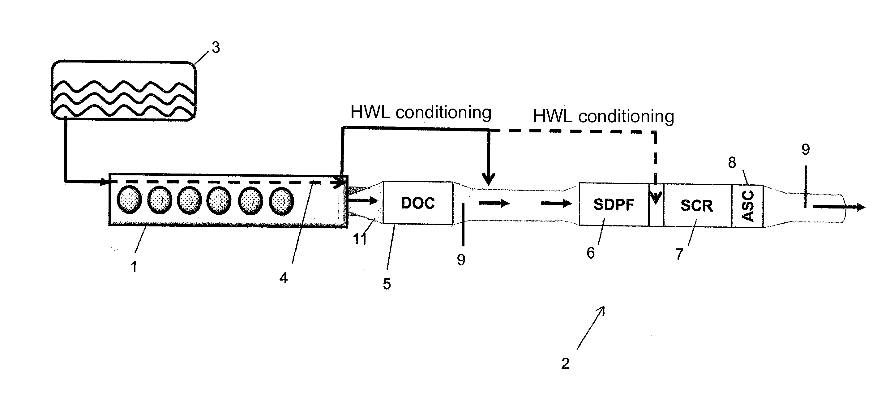
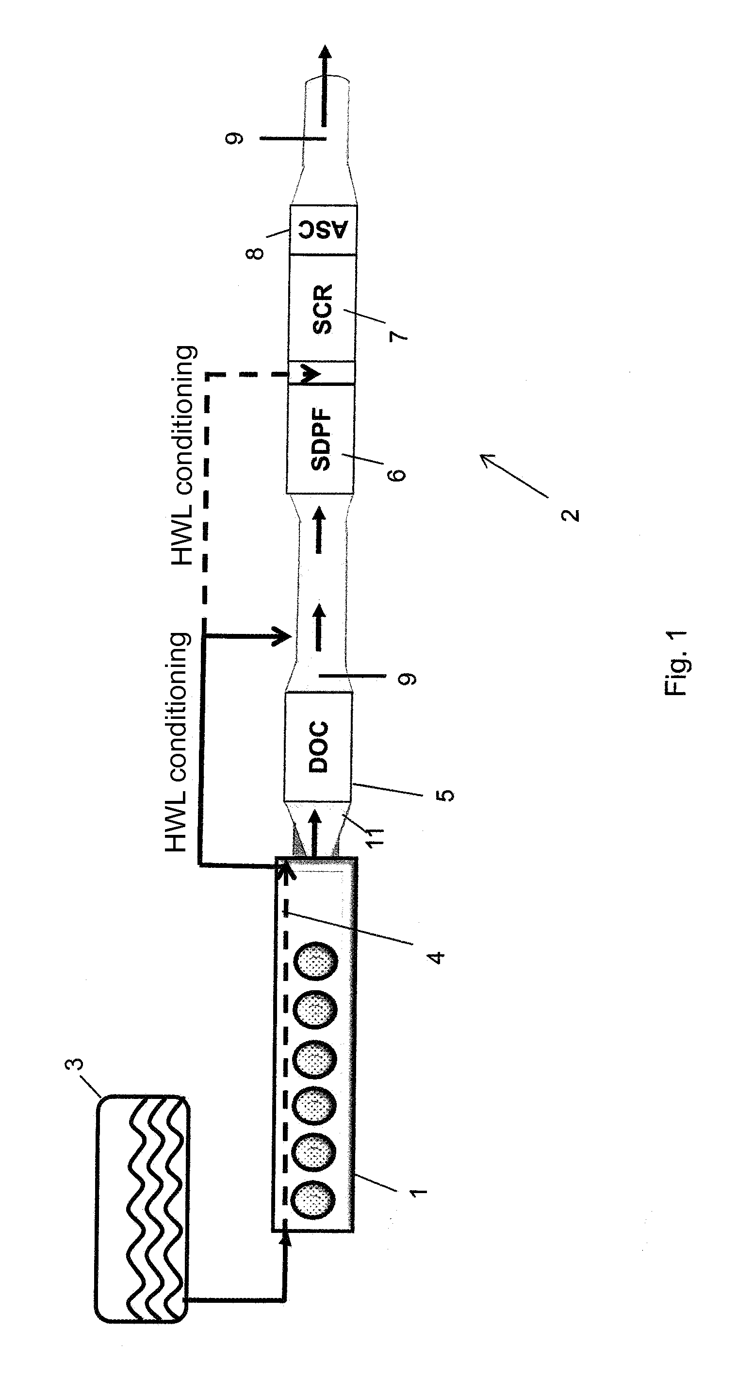
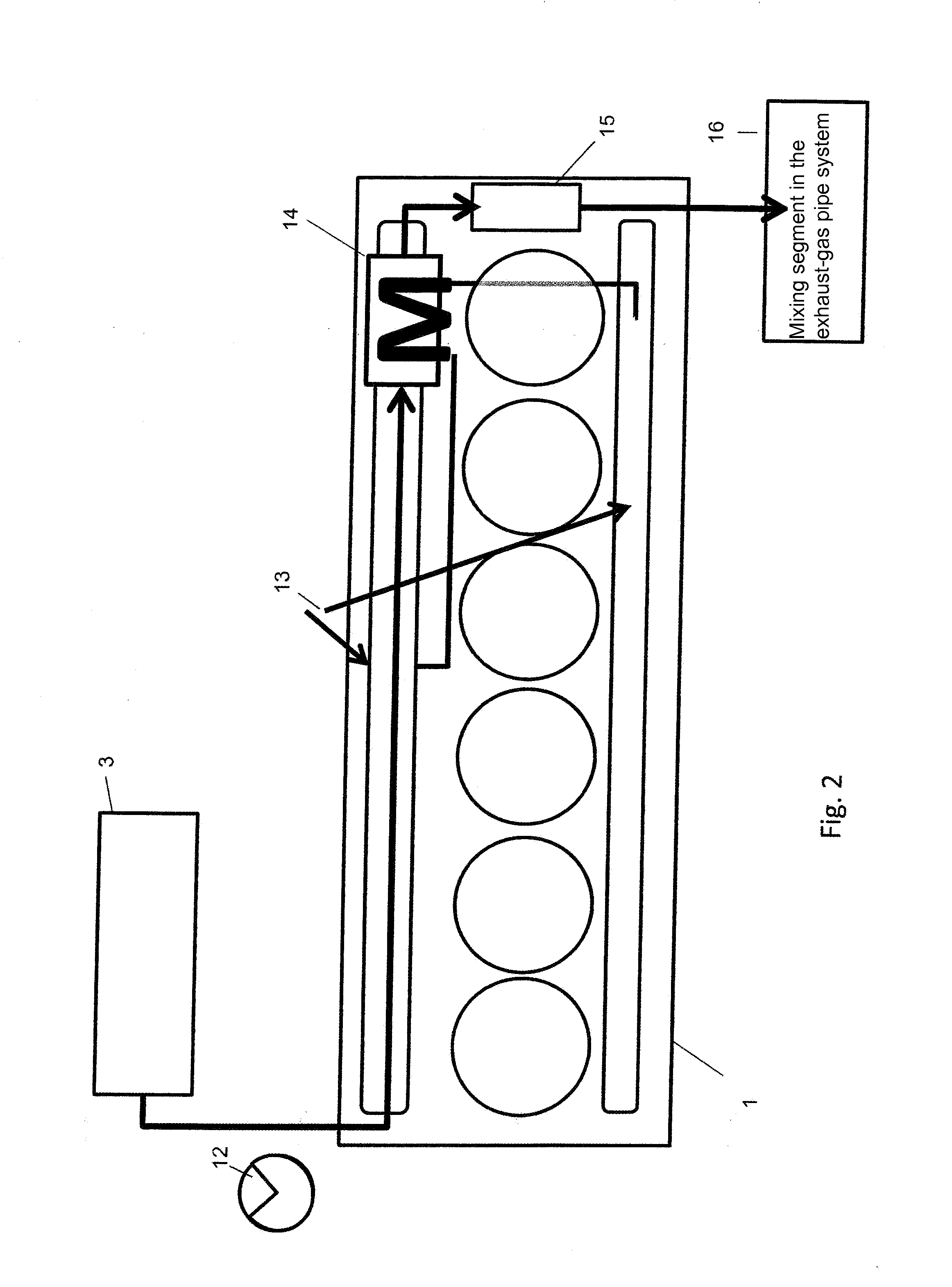
[0035]FIG. 1 shows an internal combustion engine 1 comprising an exhaust-gas line 2, a urea-water solution tank 3 and an NH3 generator 4. The NH3 generator 4 is located essentially in the area of the crankcase of the internal combustion engine 1. A NOx sensor 9 and an NH3 feeding device are arranged in the exhaust-gas line 2 between the DOC 5 and the SDPF 6 in the flow direction of the exhaust gas, and the NH3 feeding device is supplied by the NH3 generator 4. The NH3 generator 4 can also supply the NH3 feeding device between the SDPF 6 and the SCR 7 with NH3. An ammonia slip catalyst (ASC) 8 is located downstream from the SCR 7 in the flow direction of the exhaust gas. At the end of the exhaust-gas line 2, there is a NOx sensor 9. In an alternative configuration, it is provided that the NH3 generator 4 is arranged essentially in a double-walled exhaust-gas pipe 11 that has two NOx sensors 9, whereby one NOx sensor 9 is situated between the DOC 5 and the SDPF 6, while the other is b...


PUM

PropertyMeasurementUnit
Areaaaaaaaaaaa
Selectivityaaaaaaaaaa
Reduction potentialaaaaaaaaaa

Abstract

An internal combustion engine, including at least one exhaust-gas line having at least one device for the after-treatment of the exhaust gas and at least one urea-water solution tank, whereby the urea-water solution tank 3 is located close to the engine, is provided.

Description

[0001]This claims the benefit of German Patent Application DE 10 2014 001 879.2, filed Feb. 14, 2014 and hereby incorporated by reference herein.BACKGROUND[0002]The invention relates to an internal combustion engine. Such internal combustion engines are known, for example, from German patent document DE 103 48 800, which discloses a method to control a reductant feed system comprising at least one heating element. Upstream, the feed system is connected to an SCR catalytic converter. During the air-assisted injection of the reductant into the feed system, an evaporated mixture of air and reductant is formed over the heated element, and this mixture is introduced into an exhaust-gas mixture that is entering the SCR catalytic converter. An aqueous urea solution is employed as the reductant. The entire feed system, including the mixing unit for the urea-water solution and air as well as the heating element or evaporator unit, is integrated downstream from the SCR catalytic converter int...

Claims


Application Information

Patent Timeline
IPC IPC(8): B01D53/94F01N3/035
CPCF01N3/035B01D53/9477F01N3/106F01N3/2066F01N2240/02F01N2340/02F01N2340/06F01N2570/18F01N2610/02F01N2610/10F01N2610/14F01N2610/1453F01N13/009Y02T10/12F01N3/021F01N3/0828F01N3/2896F01N2560/026F01N3/103
Inventor WITTROCK, MEIKEKLEIN, ULFLEYH, GERALD
Owner DEUTZ AG
Why Eureka
Try Eureka