
Chemical mechanical polishing conditioner with high performance

a polishing conditioner and mechanical technology, applied in the direction of grinding devices, metal-working devices, abrasive surface conditioning devices, etc., can solve the problems of reduced polishing performance and efficiency, and the structure of the cutting edge angle of the abrasive particles cannot avoid the fixing of the cutting edge angle, so as to achieve the optimal cutting ability and high performance

Inactive Publication Date: 2015-08-20
KINIK
View PDF5 Cites 4 Cited by
  • Summary
  • Abstract
  • Description
  • Claims
  • Application Information

AI Technical Summary

Benefits of technology

The present invention provides a chemical mechanical polishing conditioner with high performance, which can control the profiles of each abrasive particle to achieve an optimum cutting ability. The abrasive particles can avoid limitations based on their crystal form to obtain an optimum cutting edge angle. The conditioner can be used to manufacture high-quality polished surfaces with specific cutting edge angles, crystal structures, tip heights, or tip orientations. The method for manufacturing the conditioner involves providing a substrate with a binding layer and plurality of abrasive particles, and treating each abrasive particle with a surface processing treatment to achieve specific cutting characteristics. The abrasive particles can be fixed on the substrate or disposed on metal fixing seats and fixed on the substrate using the binding layer. This conditioner is different from traditional conditioners as it can be designed with specific profiles of the abrasive particles, not limited to their crystal forms. Overall, this invention offers a chemical mechanical polishing conditioner with improved performance and flexibility for achieving the optimum cutting ability.

Problems solved by technology

When the polishing pad has been used for a certain period of time, the polishing performance and efficiency are reduced because the debris produced in the polishing process may accumulate on the surface of the polishing pad.
But, the abrasive particles of the above-mentioned chemical mechanical polishing conditioner are limited to their crystal forms, such as hexoctahedron, so that cutting edge angles of the abrasive particles cannot avoid the fixing cutting edge angles due to their structures.

Method used


Image

  • Chemical mechanical polishing conditioner with high performance
  • Chemical mechanical polishing conditioner with high performance
  • Chemical mechanical polishing conditioner with high performance

Examples


example 1

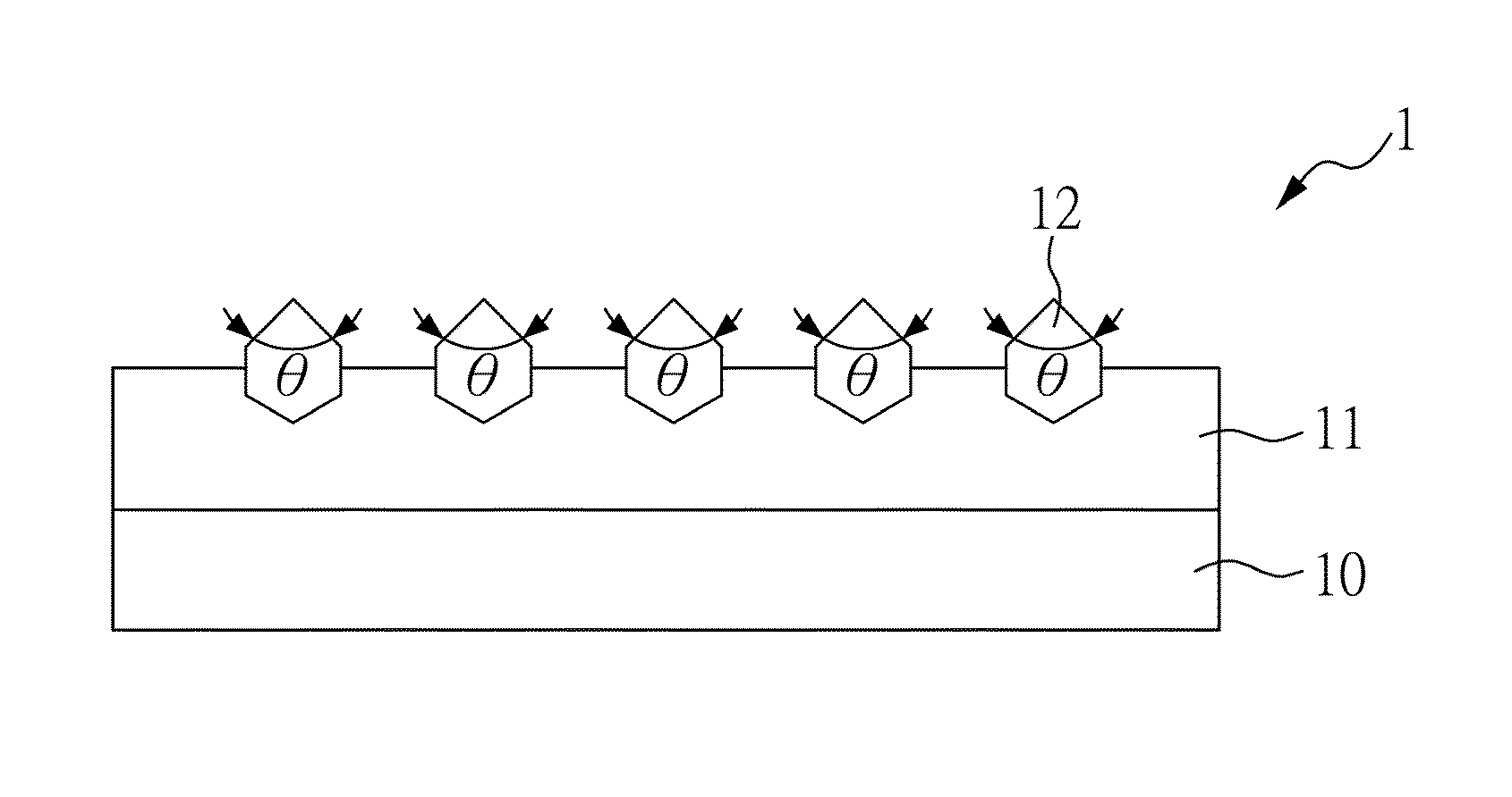
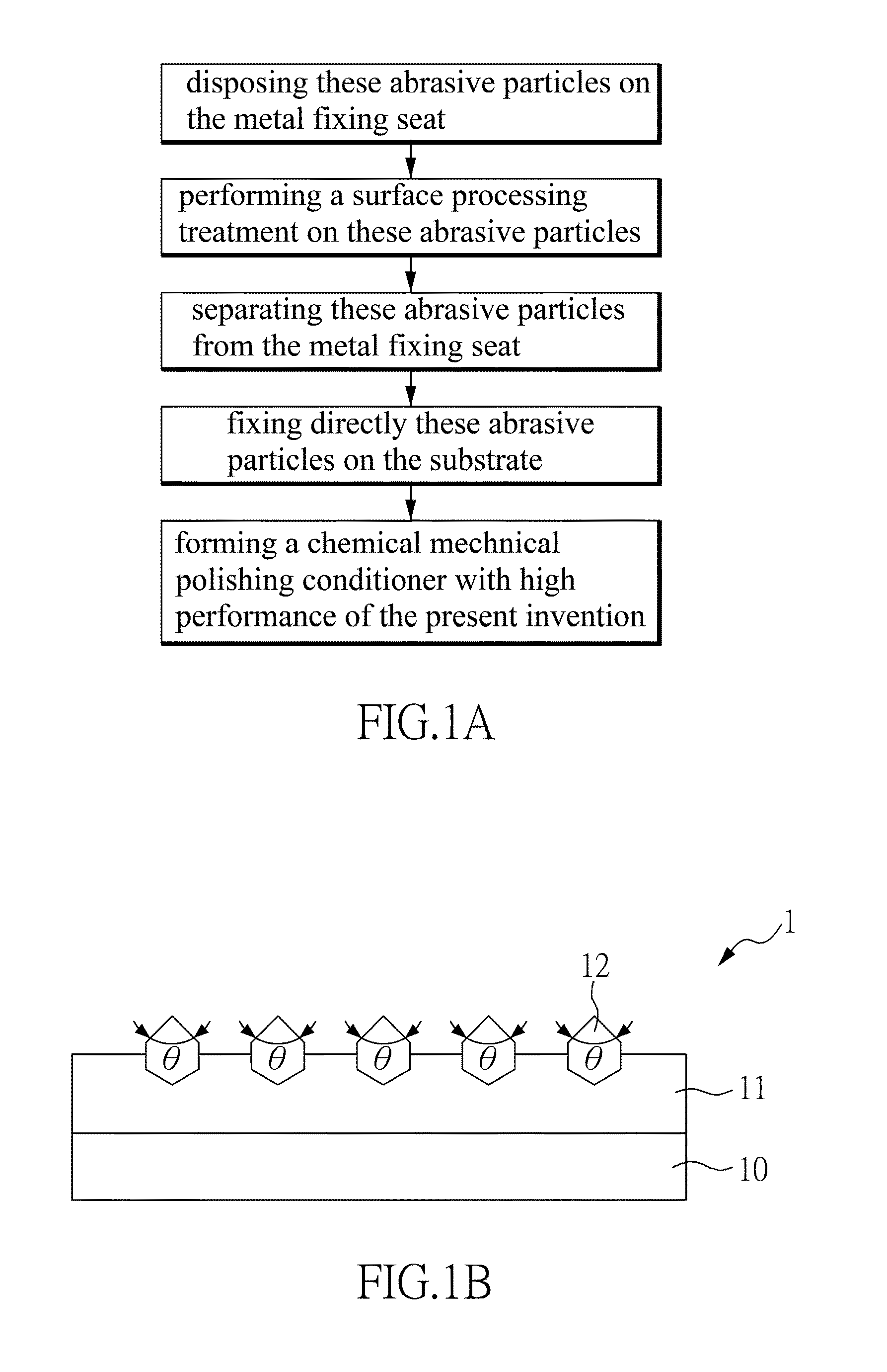
[0029]Please refer to FIGS. 1A and 1B, FIG. 1A shows a block flow diagram of a chemical mechanical polishing conditioner with high performance of the present invention, and FIG. 1B shows a schematic diagram of a chemical mechanical polishing conditioner with high performance of the present invention. Please refer to FIGS. 1A and 1B, in the chemical mechanical polishing conditioner with high performance according to Example 1 of the present invention, first, these abrasive particles 12 are disposed on a metal fixing seat (not shown); wherein the these abrasive particles 12 are artificial diamonds with particle size of 300 μm. Secondly, these abrasive particles 12 are performed a surface processing treatment, so that these abrasive particles have specific cutting edge angle (θ) of 90 degree. Please refer to FIG. 1B, theses abrasive particles can avoid limitations of theirs crystal forms based on a condition of figure of a single abrasive particle to obtain an optimum cutting edge angl...

example 2

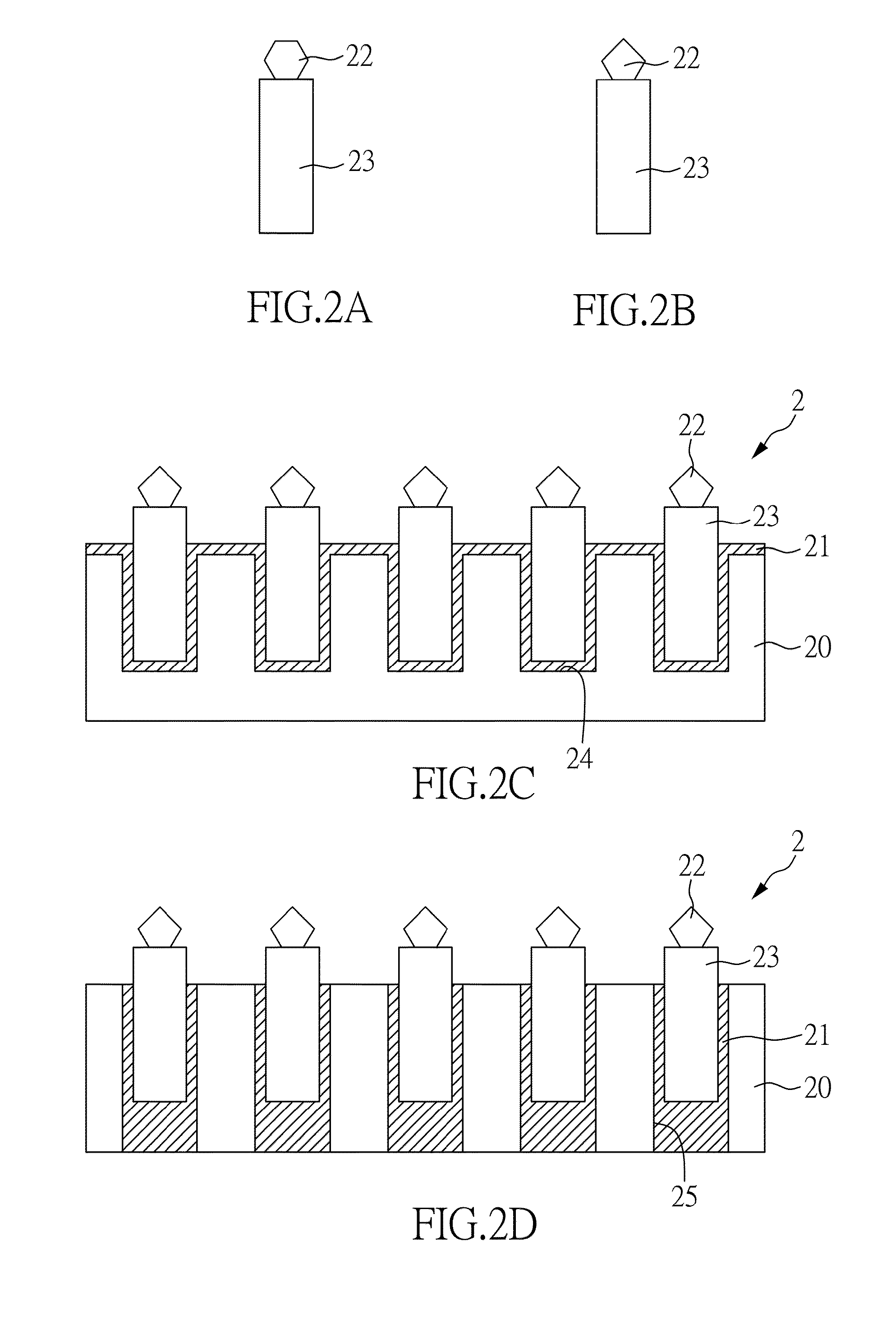
[0030]Please refer to FIG. 2, FIG. 2 shows schematic diagrams of the chemical mechanical polishing conditioner with high performance according to Example 2 of the present invention. The device of the chemical mechanical polishing conditioner 20 with high performance of Example 2 is substantially the same as the above Example 1, but the differences are that the abrasive particles 12 of Example 1 are fixed directly on the substrate by the binding layer 11, and the abrasive particles 22 of Example 2 are disposed on the metal fixing seat 23. Please refer to FIG. 2A, each abrasive particle 22 is disposed on the metal fixing seat 23 having plane top; wherein these abrasive particles 22 are artificial diamonds with particle size of 800 μm. Besides, the metal fixing seat 23 having the plane top is a cylinder figure of which the external diameter is 3 mm and each abrasive particle 22 is fixed on the metal fixing seat 23 having plane top by the abrasive binding layer (not shown in figures) ma...

example 3

[0031]Please refer to FIGS. 3A to 3C, FIGS. 3A to 3C show schematic diagrams of the chemical mechanical polishing conditioner with high performance according to Example 3 of the present invention. The device of the chemical mechanical polishing conditioner with high performance of Example 3 is substantially the same as the above Example 2, but the differences are that these abrasive particles having plane bottoms are disposed on the metal fixing seat with plane tops in Example 2, but these abrasive particles having non-plane bottoms are disposed on the metal fixing seat with blind holes at top, so that these abrasive particles having non-plane bottoms are corresponded to the metal fixing seat with blind holes at top. Please refer to FIG. 3A, first, theses abrasive particles 32 having non-plane bottoms are disposed on the metal fixing seat 33 with blind holes at top; wherein theses abrasive particles 32 are artificial diamonds with particle size of 800 μm, and the metal fixing seats ...


PUM


Abstract

The present invention relates to a chemical mechanical polishing conditioner with high performance, comprising a substrate; a binding layer disposed on the substrate; and a plurality of abrasive particles fixed directly on the substrate by the binding layer, or each abrasive particle disposed on a metal fixing seat and the substrate have a plurality of blind holes and a plurality of through holes, so that the metal fixing seats are installed into the blind holes or the through holes, and the metal fixing seat fixed on the substrate by the binding layer; wherein the abrasive particles are treated by a surface processing treatment to make the abrasive particles have specific cutting edge angles, crystal structures, tip heights, or tip orientations. Therefore, the present invention can control the profile of each abrasive particle to accomplish the best polishing performance.

Description

CROSS REFERENCE TO RELATED APPLICATION[0001]This application claims the benefits of the Taiwan Patent Application Serial Number 103105288, filed on Feb. 18, 2014, the subject matter of which is incorporated herein by reference.BACKGROUND OF THE INVENTION[0002]1. Field of the Invention[0003]The present invention relates to a chemical mechanical polishing conditioner, and more particularly to a chemical mechanical polishing conditioner including a plurality of abrasive particles which are performed surface treatments.[0004]2. Description of Related Art[0005]Chemical mechanical polishing (CMP) is a common polishing process in various industries, which can be used to grind the surfaces of various articles, including ceramics, silicon, glass, quartz, or a metal chip. In addition, with the rapid development of integrated circuits, chemical mechanical polishing becomes one of the common techniques for wafer planarization because it can achieve an object of whole planarization.[0006]During ...

Claims


Application Information

Patent Timeline
Patent Type & Authority Applications(United States)
IPC IPC(8): B24B53/017B24D18/00
CPCB24B53/12B24D3/06B24B53/017B24D18/0072
Inventor CHOU, JUI-LINWANG, CHIA-CHUNLIAO, I-TSAOCHIU, CHIA-FENGLIAO, WEN-JEN
Owner KINIK
Learn More