Induction welding process and device for parts made of composite materials

a composite material and welding process technology, applied in the direction of ohmic-resistance heating, other domestic articles, electric/magnetic/electromagnetic heating, etc., can solve the problems of difficult control in terms of temperature and welding interface, difficult to manage magnetic field in order to limit the effect of effect, and difficulty in controlling process temperatur

Active Publication Date: 2015-08-20
AIRBUS OPERATIONS (SAS)
View PDF4 Cites 12 Cited by
  • Summary
  • Abstract
  • Description
  • Claims
  • Application Information

AI Technical Summary

Benefits of technology

[0022]Hence, the process according to the invention provides for the application of a uniform (homogeneous) field by means of a two-sided rather than a single-sided inductor. The homogeneity of the field lines favors a uniform temperature over the assembly of the contact walls. Moreover, the process allows the preponderance of heating by hysteresis over heating by induced currents to be optimized by applying a magnetic field in a direction of incidence relative to the principal plane at an angle other than 90° and other than zero. This allows the assembly to be heated uniformly, in particular at the contact walls of the composite material.
[0023]The generation of this uniform magnetic field allows the geometry of the assembly to be welded to be dispensed with. Consequently, it is no longer necessary, thanks to the invention, to adapt the inductor to each surface or shape of the assembly to be welded. This process can therefore be used whatever the shape and profile of the parts to be welded.

Problems solved by technology

However, the main disadvantages of this type of process are firstly the highly localized presence of conductive metal in the final product and secondly, the difficulty in controlling the temperature of the process.
These welding processes through the circulation of induced currents are therefore difficult to control in terms of temperature and welding interface.
In fact, it is difficult to manage the magnetic field in order to limit its effect exclusively to the surface carbon folds which are at the interface between the two composite materials to be welded.
Processes of this kind, with or without conductive metal, are prone to several limitations which prevent their use on an industrial scale in the aeronautical field.
In effect, the geometric design of the inductor is complex for simple planar surface geometries.
It requires simulations that call for substantial computer resources, for example an L-shape requires two weeks of simulation in order to obtain the shape of the inductor, without guaranteeing the uniformity of the heat effect.
If this distance varies, the temperature is too great or, conversely, is not great enough.

Method used


Image

  • Induction welding process and device for parts made of composite materials
  • Induction welding process and device for parts made of composite materials
  • Induction welding process and device for parts made of composite materials

Examples


first embodiment

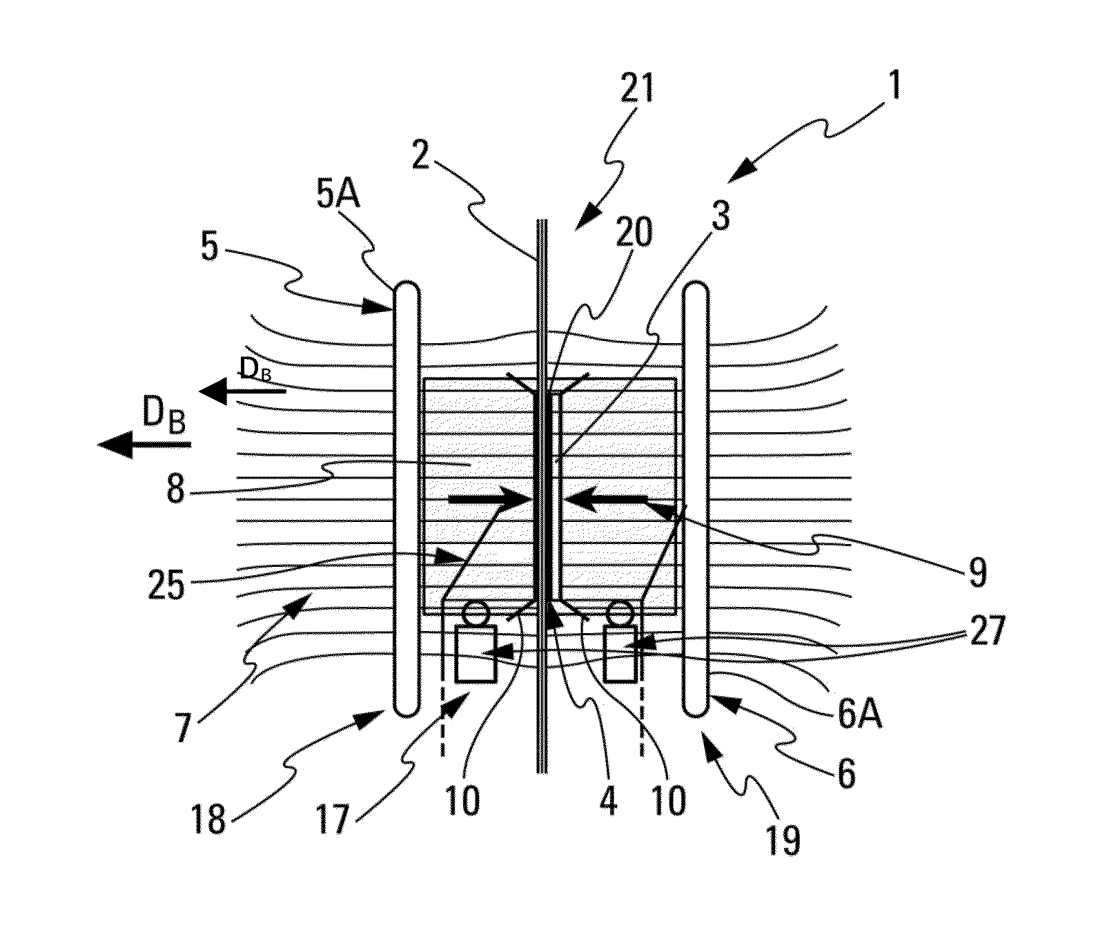
[0050]In a first embodiment, the grate or the ferromagnetic particles are embedded in a resin film compatible with those of the two parts 2 and 3 and form an interface element 20 disposed between the contact walls of the two parts 2 and 3, so that welding is carried out during the transformation of the composite materials.

[0051]According to another embodiment, the ferromagnetic particles are mixed with the composite material resin on the contact wall of at least one of the parts 2 and 3 at the time of production of the parts 2 and 3. The ferromagnetic material is present in the form of spherical ferromagnetic particles embedded in the resin, for example polysulfone (PSU), with volume fractions of between 10% and 20%. The diameter of the ferromagnetic particles is small (between 22 microns and 300 microns). The uniformity of the resin / particles mixture depends on the grade of the resin, the granulometry of the ferromagnetic material particles and also the impregnation between the res...

second embodiment

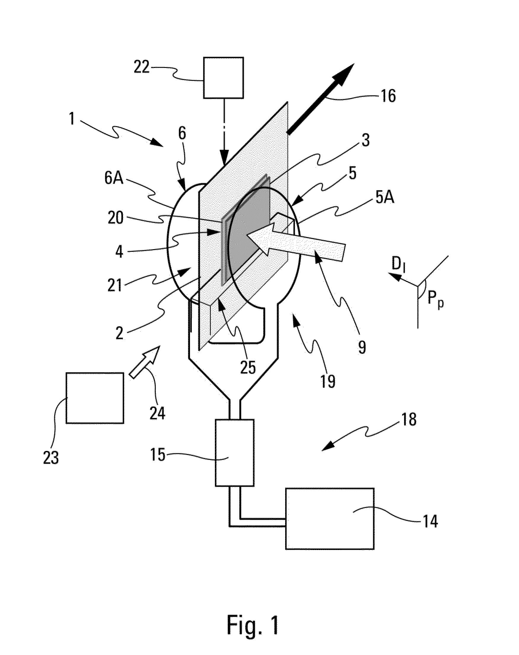
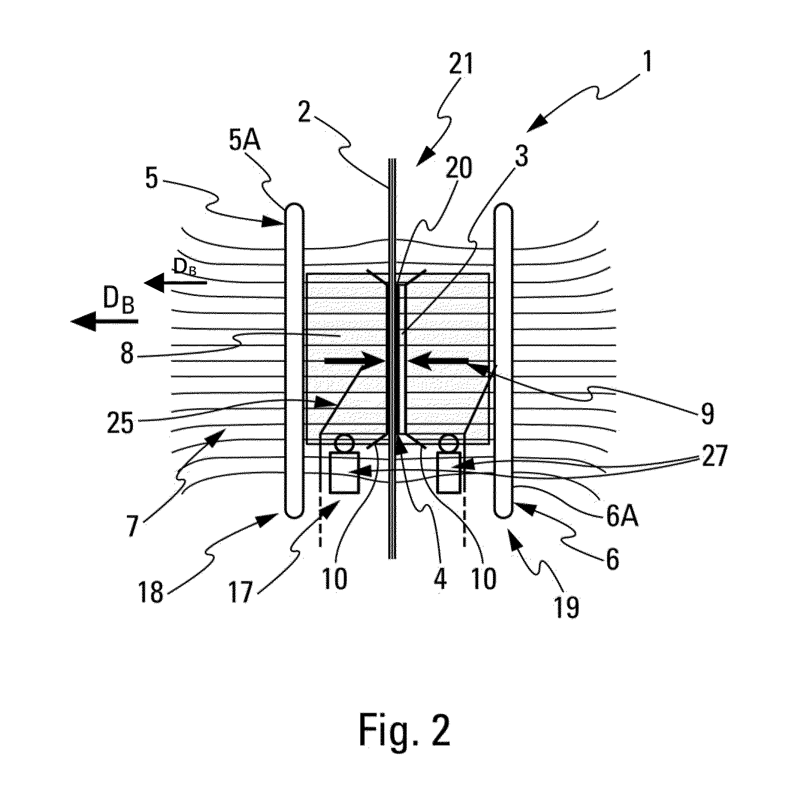
[0068]Moreover, in the invention, the device 1 further comprises means of displacement 22 which are capable of moving the assembly 21 between the coils, as indicated by an arrow 16 in FIG. 3. The assembly 21 is subjected to translational movement in zone 8 where the magnetic field 7 is uniform. The displacement speed of the assembly 21 (generated by the means of displacement 22) is controlled such that the exposure time to the magnetic field 7 (between the coils) is sufficient to reach the transformation temperature of the composite materials and thereby achieve welding of the parts 2 and 3.

[0069]In this second embodiment, a production line allows the assembled parts 2 and 3 to be produced by making them circulate in an assembly between the two coils.

[0070]The magnetic field 7 is applied with defined parameters depending on the nature of the ferromagnetic material, the granulometry of the particles or of the grate. In a preferred embodiment, the frequencies are raised (in the order ...


PUM

PropertyMeasurementUnit
temperatureaaaaaaaaaa
diameteraaaaaaaaaa
diameteraaaaaaaaaa

Abstract

A device comprising at least one pressure generation unit and a heating unit, the heating unit comprising a two-sided inductor and being configured to generate a uniform alternating magnetic field in an assembly comprising two parts made of composite materials comprising carbon fibers embedded in a resin and a field absorber. The field absorber is configured to absorb the magnetic field and comprising a ferromagnetic material. The field absorber is arranged at the contact walls of the two parts, so as to heat them to at least a transformation temperature of the resin.

Description

CROSS-REFERENCES TO RELATED APPLICATIONS[0001]This application claims the benefit of the French patent application No. 1451293 filed on Feb. 18, 2014, the entire disclosures of which are incorporated herein by way of reference.BACKGROUND OF THE INVENTION[0002]The present invention relates to a process and a device for induction welding parts made of composite materials. The invention relates in particular to the assembly of parts made of composite materials in the aeronautical field.[0003]The parts made of composite materials generally comprise carbon fibers embedded in a resin which are deposited by drape forming, for example, so as to create folds superposed one on top of the other. In each fold the fibers are aligned in a main direction (0°, 45°, 90°). The planes of the carbon fiber folds are parallel to one another and define a plane referred to as the principal plane. Moreover, the methods involved in producing a part of this kind generate points of contact between the folds, t...

Claims


Application Information

Patent Timeline
Patent Type & Authority Applications(United States)
IPC IPC(8): B32B37/06
CPCB29L2031/3076B29C66/91651B29C65/3612B29C65/364B29C65/3668B29C65/3676B29C65/368B29C65/7841B29C66/1122B29C66/3494B29C66/472B29C66/7212B29C66/816B29C66/81811B29C66/91411B29C66/91921B29C66/9441H05B6/105H05B6/40B29C66/932B29K2995/0008B29C66/71H05B2206/023B29K2307/04B29K2081/06B29K2071/00B32B37/06B32B2310/00
Inventor CHOTARD, FLORIANCOLLART, CYRILLETRICHET, I, DIDIERFOULADGAR, JAVAD
Owner AIRBUS OPERATIONS (SAS)
Why Eureka
Try Eureka