Eureka AIR delivers breakthrough ideas for toughest innovation challenges, trusted by R&D personnel around the world.

Floating tower frame for ocean current turbine system

Active Publication Date: 2015-09-17
AQUANTIS
View PDF9 Cites 10 Cited by
  • Summary
  • Abstract
  • Description
  • Claims
  • Application Information

AI Technical Summary

Benefits of technology

The present invention is a marine current turbine system that can be easily deployed and controlled with directionally changing fluid flows. It is efficient, scalable, and offers safe servicing and maintenance options. The turbines can yaw to capture the power of directionally changing fluid flows or shed load if the current speed exceeds the turbine's rated capacity.

Problems solved by technology

Relative to wind, the energy potential wave and tidal resources is the least understood and its technology is the least mature.
System reliability is of particular importance, since the logistics of at-sea maintenance is likely to be limited by accessibility, and windows of acceptable weather and sea-states conditions, therefore the costs can be high.
Furthermore any system deployed in the ocean must be able to survive large waves and storms, raising the capital cost and maintenance.
This system is expensive due to the structural requirements necessary for dealing with the overturning moment of the whole structure from thrust load of the current on the rotors.
This limits deployment to shallow locations.
Installation is costly since it is only possible during short periods between tidal flows.
Servicing just one rotor results in raising all the rotors above the surface and shutting down all of the rotors (not just the one requiring servicing) of the entire system resulting in significant lost production.
Moreover, the design requires both rotors to operate simultaneously since a shutdown of one rotor would yaw the rotor support structure toward alignment with the flow rather than squarely facing the flow, significantly reducing production.
This system is also expensive due to structural requirements to deal with the overturning moment of the whole structure from thrust load of the current on the rotors.
In a tidal flow, this would be difficult, as the flow in one direction drops off and waters calm, providing a brief window for servicing operations before the flow reverses, at which point the whole floating structure swings around to an opposite position on the surface due to the opposite flow direction.
This design appears costly, complex, and dangerous.
It also requires a much larger operating footprint represented by the full surface of the operating water column perimeter, which results in higher power collection cabling costs, lower power generating density per unit of seafloor area, and the potential for rotor entanglement with the mooring lines.
These prior art systems are not capable of producing cost-effective, utility-scale electrical power output to meet modern energy needs.

Method used


Image

  • Floating tower frame for ocean current turbine system
  • Floating tower frame for ocean current turbine system
  • Floating tower frame for ocean current turbine system

Examples


Embodiment Construction

[0029]Preferred embodiments of the present invention and their advantages may be understood by referring to FIGS. 1-11, wherein like reference numerals refer to like elements. The present invention may be utilized in any type of moving fluid, e.g., water flow, environment such as, but not limited an ocean current environment or tidal current environment. Although the present invention is described in the context of electrical power generation, it can also be used to provide high pressure seawater for reverse osmosis fresh water production.

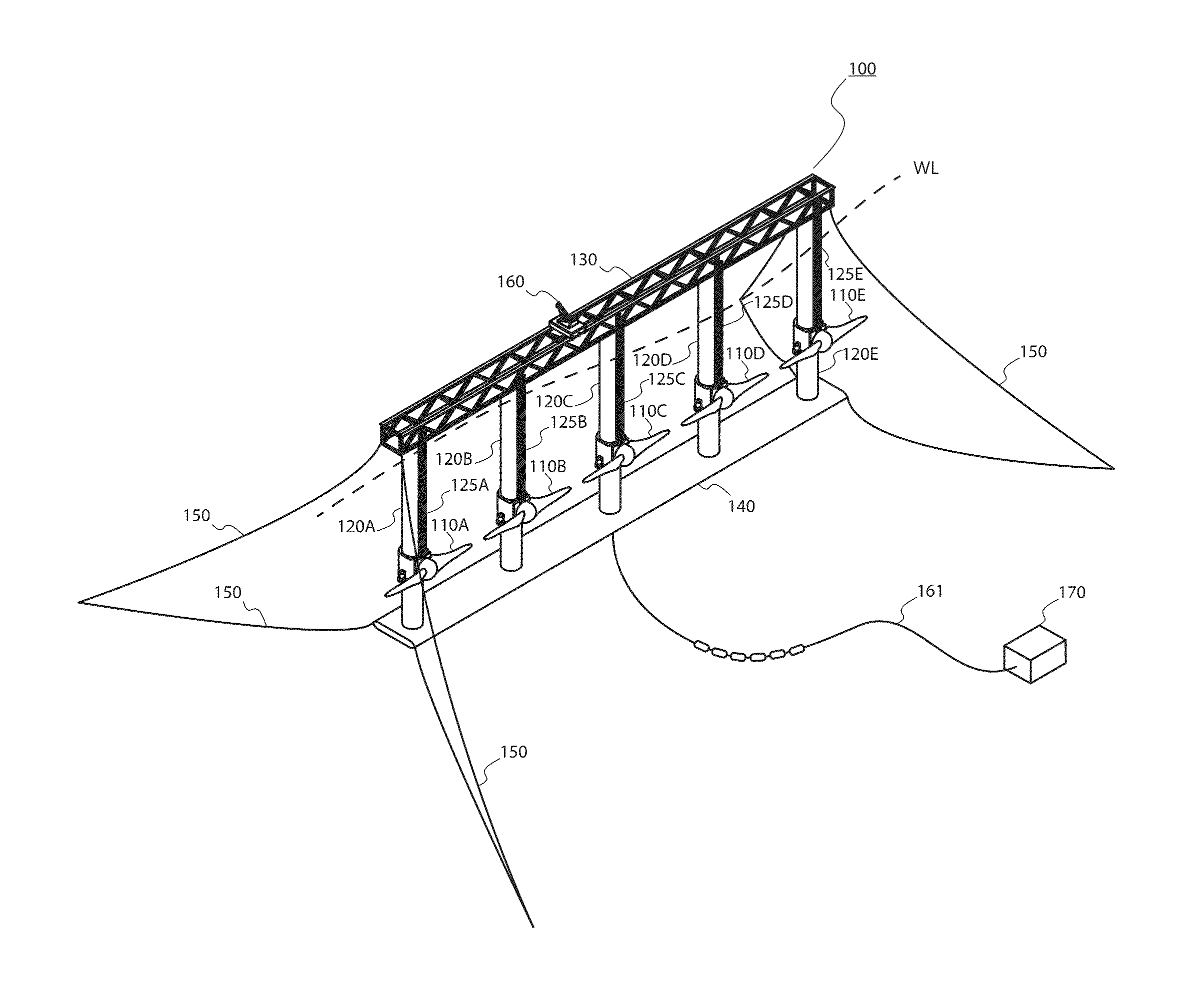
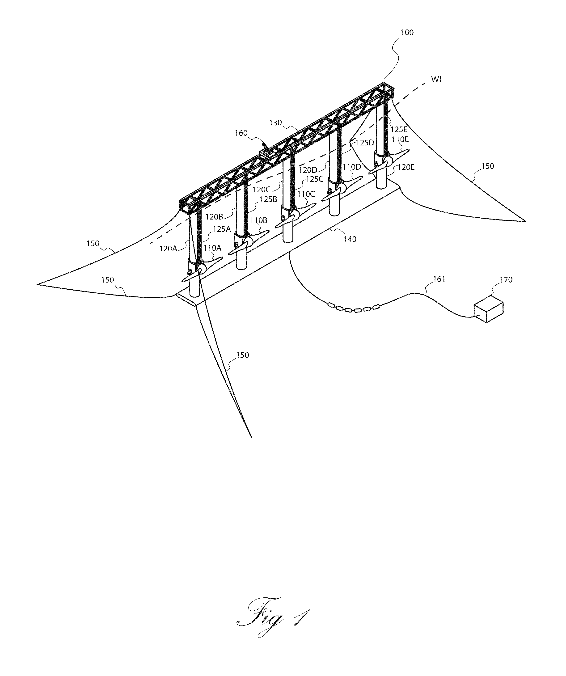
[0030]FIG. 1 illustrates an ocean current turbine system 100 according to an embodiment of the invention. The ocean current turbine system 100 comprises a plurality of current turbines 110A-E and respective floating towers 120A-E, each turbine 110 disposed on its own tower 120. The towers 120A-E are located (when in operation) between a top structural connecting member 130 above the water line “WL” and a bottom structural connecting member 140 belo...


PUM


Abstract

The present invention provides a floating tower frame for an ocean current turbine system comprising multiple rotors, which is designed to generate electrical power or high pressure seawater for reverse osmosis or fresh water production from steady (gyre) or tidal currents. Turbines are mounted near the base of a plurality of floating towers held in parallel between a horizontal truss structure above water and a horizontal wing at the base of the towers, below the surface. The center of gravity of the system is located in the bottom one third of the towers below the water line, while the center of buoyancy is in the top third of the towers below the surface, and the entire structure floats vertically, with respect to the towers.

Description

BACKGROUND OF THE INVENTION[0001]1. Field of Invention[0002]This invention relates to ocean current turbines and, more specifically, to a floating tower frame turbine system to generate electrical power and / or to produce fresh water from seawater.[0003]2. Description of Related Art[0004]Ocean currents are a major, largely untapped energy resource. Research and development in this area is driven by the need to generate electricity from renewable energy resources, particularly in view of the rising level of CO2 in the earth's atmosphere from combustion of carbon fuels and the resulting impact on climate from global warming.[0005]An ocean current is a continuous, directed movement of seawater generated by the forces acting upon this flow, such as breaking waves, wind, Coriolis effect, evaporation, temperature and salinity differences (cabbeling), and tides caused by the gravitational pull of the Moon and the Sun. Depth contours, shoreline configurations and interaction with other curre...

Claims


Application Information

Patent Timeline
IPC IPC(8): F03B17/06
CPCF03B17/06F03B13/264F05B2240/40F05B2240/93F05B2260/02F05B2270/1011F05B2270/20F05B2270/327F03B17/061Y02P70/50Y02E10/30Y02E10/20
Inventor DEHLSEN, JAMES G.P.
Owner AQUANTIS
Why Eureka
Eureka Blog
Learn More