
Protective sheet for rear surface of solar cell

a solar cell and rear surface technology, applied in the direction of adhesives, semiconductor devices, adhesive types, etc., can solve the problems of poor adhesion of materials, inability to provide sufficient adhesion strength, etc., to suppress the appearance of solar cell modules, suppress zipping, and good adhesion strength

Active Publication Date: 2015-09-17
TOYO ALUMINIUM KK
View PDF5 Cites 2 Cited by
  • Summary
  • Abstract
  • Description
  • Claims
  • Application Information

AI Technical Summary

Benefits of technology

The patent text describes a solar cell rear surface protection sheet that can effectively stick multiple substrates together, even if they are made of poorly adhesive materials. This sheet helps prevent the occurrence of bubbling or zipping when the substrates are laminated. The use of this sheet also helps improve the long-term appearance of the resulting solar cell module.

Problems solved by technology

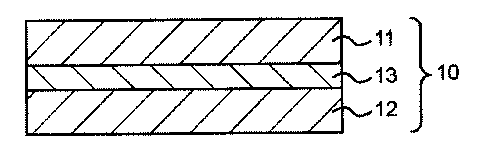
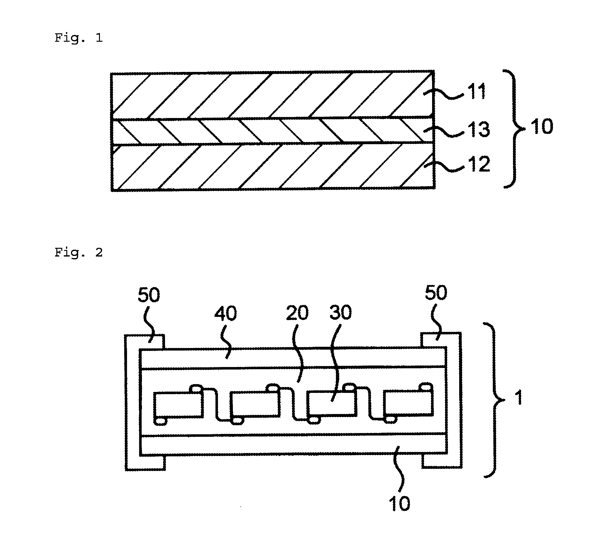
In FIG. 1, particularly if the adhesive 13 were to have poor performance, the films 11 and 12 would peel off, thus impairing the appearance of the solar cell rear surface protection sheet 10 over time.
However, LLDPE, polyester films, fluorine-containing films, inorganic vapor deposited films, etc., are materials with poor adhesion.
Thus, an inability to provide sufficient adhesion strength and the problem of sudden peeling, called zipping, are likely to occur.

Method used


Image

  • Protective sheet for rear surface of solar cell
  • Protective sheet for rear surface of solar cell

Examples


example 1

[0043]A linear low-density polyethylene (LLDPE) resin composition was prepared by adding 25 kg of titanium oxide particles to 100 kg of a polyethylene resin with a density of 0.91 g / cm3 and sufficiently kneading the mixture. This LLDPE resin composition was extruded with an extruder to obtain an inner layer substrate with a thickness of 50 μm.

[0044]A polyethylene terephthalate film with a thickness of 250 μm (produced by Toyobo Co., Ltd.; Toyobo ester film E5102) was prepared as an intermediate layer substrate having excellent electrical insulation.

[0045]A PVF film (produced by DuPont, 38 μm) was prepared as an outer layer substrate.

[0046]As an adhesive, a urethane resin was obtained by mixing 7.8 parts by weight of Lexp 11-1, an isocyanate compound produced by Henkel Japan Ltd. (containing a xylylene diisocyanate monomer in an amount of 30 parts by weight and hexamethylene diisocyanate isocyanurate in an amount of 70 parts by weight; the NCO group percentage is 28.7%), with 100 par...

example 2

[0048]A solar cell rear surface protection sheet was obtained in the same manner as in Example 1 except that Lexp 10-4 produced by Henkel Japan Ltd. (using 10 parts by weight of acrylonitrile instead of 5 parts by weight as in Lexp 10-3) was used as an acrylic polyol.

example 3

[0049]A solar cell rear surface protection sheet was obtained in the same manner as in Example 1 except that Lexp 10-5 produced by Henkel Japan Ltd. (using 15 parts by weight of acrylonitrile instead of 5 parts by weight as in Lexp 10-3) was used as an acrylic polyol.


PUM

PropertyMeasurementUnit
glass transition temperatureaaaaaaaaaa
hydroxyl valueaaaaaaaaaa
thicknessaaaaaaaaaa

Abstract

This invention provides a solar cell rear surface protection sheet comprising two or more substrates laminated together by means of an adhesive, the adhesive comprising a urethane resin obtained by mixing an acrylic polyol, an isocyanate compound, 3-glycidoxypropyltriethoxysilane, and tin octylate, whereinthe acrylic polyol being obtained by polymerizing polymerizable monomers, the polymerizable monomers comprising a hydroxyl group-containing monomer and other monomers, the other monomers comprising acrylonitrile,the isocyanate compound comprising both a xylylene diisocyanate monomer and hexamethylene diisocyanate isocyanurate, the xylylene diisocyanate monomer being is present in an amount of 20 to 40 wt %, and the hexamethylene diisocyanate isocyanurate is present in an amount of 80 to 60 wt % andthe equivalent ratio of isocyanate groups of the xylylene diisocyanate monomer and the hexamethylene diisocyanate isocyanurate to hydroxyl groups of the acrylic polyol being 1.0 to 3.0.

Description

TECHNICAL FIELD[0001]The present invention relates to a solar cell rear surface protection sheet and a solar cell module obtained using the solar cell rear surface protection sheet.BACKGROUND ART[0002]Making solar cells practical as energy sources has been promoted. Various types of solar cells have been developed. Known typical solar cells include silicon-based solar cells, inorganic compound-based solar cells, organic solar cells, and other solar cells.[0003]A solar cell module has a front surface protection sheet disposed on the side on which sunlight is incident, to protect the surface. The solar cell module also has a solar cell rear surface protection sheet (solar cell back sheet) disposed on the opposite side to protect power generation cells. Such solar cell rear surface protection sheets are required to have weatherability, water resistance, heat resistance, moisture proof properties, gas barrier properties, and like properties to minimize deterioration in the long-term per...

Claims


Application Information

Patent Timeline
Patent Type & Authority Applications(United States)
IPC IPC(8): H01L31/049H01L31/048
CPCH01L31/0481H01L31/049C08G18/6225C08G18/725C08G18/7642C08G18/792C09J175/04Y02E10/50
Inventor SEKIGUCHI, FUMIYAMAEDA, DAISUKESARUWATARI, MASATAKA
Owner TOYO ALUMINIUM KK
Learn More