
Exhaust Gas System

Active Publication Date: 2015-10-01
DAIMLER AG
View PDF4 Cites 6 Cited by
  • Summary
  • Abstract
  • Description
  • Claims
  • Application Information

AI Technical Summary

Benefits of technology

The patent describes a system for mixing reducing agent with exhaust gas in an efficient and effective way. The system has an intake opening and a transfer pipe with a perpendicular axis, which allows the exhaust gas to flow through without losing energy. This results in a high swirl rate, which facilitates mixing of the reducing agent with the exhaust gas. The system also has a shorter mixing section, which reduces the need for a separate mixer and avoids pressure loss. The technical effects of this patent are improved mixing and vaporization of reducing agent with exhaust gas, which leads to faster hydrolysis and thermolysis of urea and simplifies the overall design of the exhaust gas system.

Problems solved by technology

A relatively intricate flow path for the exhaust gas is formed in this way and is associated with a pressure loss.
For this reason, a mixing section arranged downstream of the intake openings for vaporizing and mixing reducing agent with the exhaust gas must be made comparatively long, which has a detrimental effect on the installation length of the second exhaust gas duct element and therefore also the exhaust gas system as a whole.

Method used


Image

  • Exhaust Gas System
  • Exhaust Gas System
  • Exhaust Gas System

Examples


Embodiment Construction

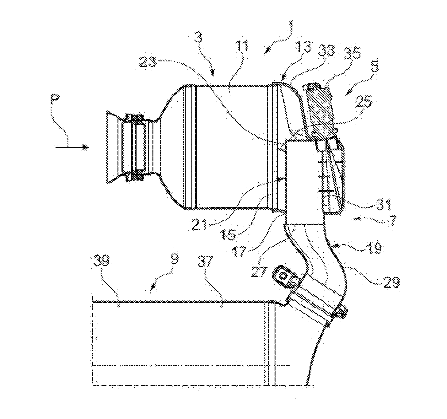
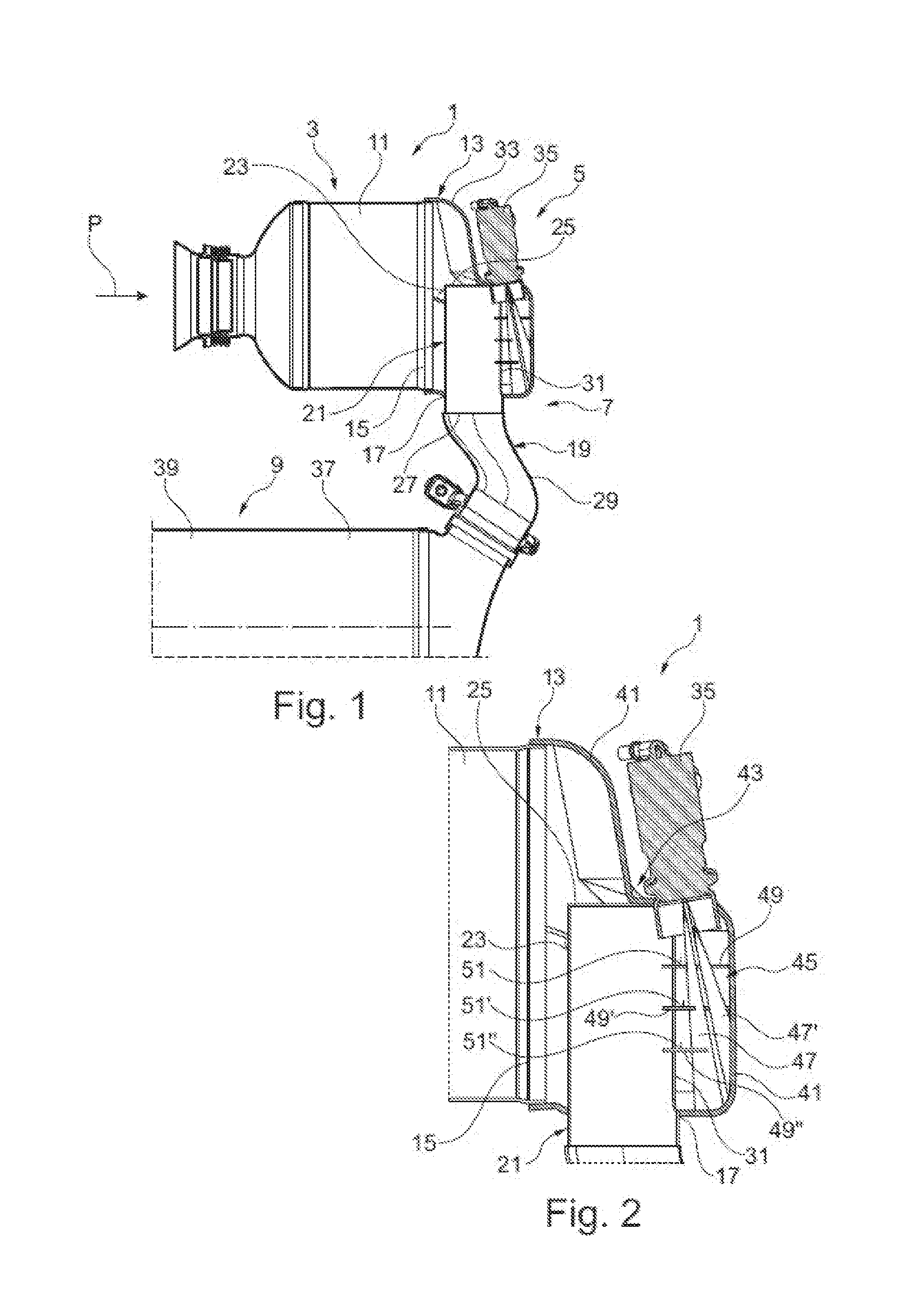
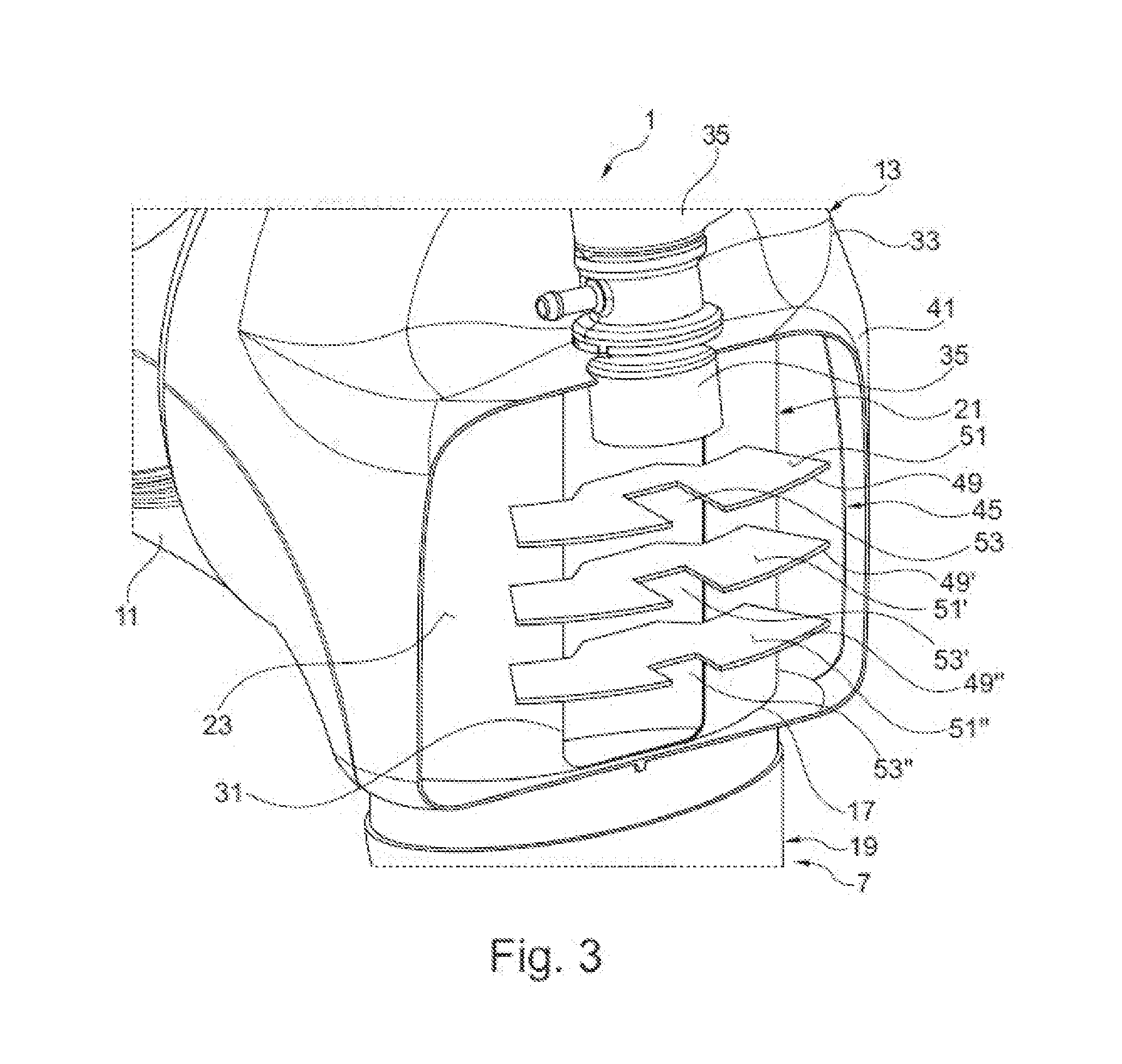
[0048]FIG. 1 shows a schematic longitudinal sectional diagram of a first exemplary embodiment of an exhaust gas system 1. This is used for exhaust gas routing and exhaust gas aftertreatment in a motor vehicle. It comprises a first exhaust gas aftertreatment element 3, a mixing device 5 by means of which a reducing agent is mixed with the exhaust gas flow, wherein the mixing device 5 has a mixing section 7, and a second exhaust gas aftertreatment element 9.

[0049]Coming from an internal combustion engine, exhaust gas flows in the direction of an arrow P into the first exhaust gas aftertreatment element 3. It flows through this and hence passes to the mixing device 5, where it is mixed with the reducing agent. Mixing and homogenization is intensified along the mixing section 7 until the exhaust gas finally enters the second exhaust gas aftertreatment element 9. This, in turn, leaves it in the direction of an exhaust pipe which is not shown. Here, it is in no way excluded that further e...


PUM


Abstract

A system for exhaust gas routing and aftertreatment in a motor vehicle includes a first exhaust gas duct element, which has an inlet opening and an outlet opening, and a second exhaust gas duct element, which has a transfer pipe having a longitudinal axis and having a sleeve surface and a first closed end. An intake opening is provided in the sleeve surface adjacent to the closed end. The transfer pipe projects into the outlet opening and is accommodated in the first exhaust gas duct element by its closed end and the intake opening, so that exhaust gas flowing in through the inlet opening in a first direction can flow through the intake opening and into the transfer pipe and flow—viewed in the direction of the longitudinal axis of the transfer pipe—in the transfer pipe through the outlet opening out of the first exhaust gas duct element. The system also includes an injector unit fixed to the first exhaust gas duct element for introducing a reducing agent into an exhaust gas flow flowing through the first and the second exhaust gas duct element.

Description

BACKGROUND AND SUMMARY OF THE INVENTION[0001]Exemplary embodiments of the invention relate to an exhaust gas system for exhaust gas routing and exhaust gas aftertreatment in a motor vehicle.[0002]Exhaust gas systems of the kind addressed here are generally used for routing the exhaust gas within an exhaust gas train of an internal combustion engine and for aftertreatment of the exhaust gas, in particular for reducing a particulate and / or harmful substance concentration. Typically, in particular for reducing nitrogen oxides, reducing agents in an initial liquid state, such as mineral oil fuel or an aqueous urea solution, are injected into the exhaust gas flowing through the exhaust gas system. In order to obtain an efficient reduction of hazardous substances and a chemical reaction that is as complete as possible, it is necessary to vaporize the reducing agent and distribute it is uniformly as possible in the exhaust gas flow. If an aqueous urea solution is used, the urea must be con...

Claims


Application Information

Patent Timeline
IPC IPC(8): F01N3/20F01N13/00
CPCF01N13/009F01N3/20F01N3/2066F01N2240/20F01N2470/18F01N2610/02F01N2610/102F01N2610/1453F01N3/2892Y02A50/20Y02T10/12
Inventor BRAUN, TILLMANNKEPPELER, BERTHOLDKOBIELA, BERNHARDMACKENSEN, ALEXANDERPEPE, ANTONIOSCHMIDT, TIMOSCHROEPEL, MICHAEL
Owner DAIMLER AG
Learn More