Inductive power transfer system and method for operating an inductive power transfer system

a technology of inductive power transfer and inductive power, which is applied in the direction of charging stations, electric vehicle charging technology, transportation and packaging, etc., can solve the problems of low switching loss, high leakage flux of this transformer, and additional conduction loss in the resonant circuit, so as to achieve the effect of minimizing switching loss

Inactive Publication Date: 2015-10-01
ABB (SCHWEIZ) AG
View PDF13 Cites 94 Cited by
  • Summary
  • Abstract
  • Description
  • Claims
  • Application Information

AI Technical Summary

Benefits of technology

[0015]An exemplary method for controlling an inductive power transfer system for supplying electrical power from a transmitter-side subsystem connectable to a mains to a receiver-side subsystem that is connectable to a load is disclosed, the inductive power transfer system that includes: a transmitter coil and a receiver coil; a transmitter-side power converter having a mains rectifier stage to power a transmitter-side dc-bus; a transmitter-side inverter stage with a controllable turn-off time of switches of the transmitter-side inverter stage to supply the transmitter coil with an alternating current; and a receiver-side power converter including a receiver-side rectifier stage to rectify a voltage induced in the receiver coil and to power a receiver-side dc-bus and a receiver-side charging converter arranged to control a receiver-side dc-bus voltage U2,dc according to a corresponding reference value U2,dc*; the method comprising the steps of: determining a value that is indicative of a power transfer efficiency of the power transfer and calculating, from this value indicative of the power transfer efficiency, reference values U1,dc*, U2,dc* for a transmitter-side dc-bus voltage U1,dc and a receiver-side dc-bus voltage U2,dc, controlling the mains rectifier stage for the transmitter-side dc-bus voltage U1,dc of the transmitter-side dc-bus to follow the corresponding reference value U1,dc*; controlling the receiver-side charging converter for the receiver-side dc-bus voltage U2,dc of the receiver-side dc-bus to follow the corresponding reference value U2,dc*; and controlling the turn-off time of the switches of the transmitter-side inverter stage to at least minimize switching losses in the transmitter-side inverter stage transmitter-side inverter stage.

Problems solved by technology

Due to the large air gap inherent to the technology, the leakage flux of this transformer is high.
While the switching frequency ensures Zero-Voltage Switching (ZVS) of the power semiconductors of the full-bridge inverter and leads to low switching losses, it causes additional conduction losses in the resonant circuit.
This results in reactive current components in both coils that cause conduction losses additional to those caused by the specified active component of the current.
Moreover, the current that has to be switched off by the semiconductors of the full-bridge inverter 9 can also be increased due to the reactive current components, which depending on the employed type of semiconductor can also cause additional switching losses.
587-597, February 2013, the charge stored in the junction of the IGBTs can lead to high tail-currents which can cause significant switching losses despite the ZVS conditions.
However, the switching losses of the power semiconductors of the full-bridge inverter can still be high due to high tail-currents of the IGBTs.
They can present a limiting factor in the system design and make a compact realization of the converter difficult due to high cooling specifications.
While this structure offers a higher modularity, the system efficiency is reduced by the higher number of conversion stages.
Additionally, the higher number of components for the cascaded system makes a compact realization of the system challenging.

Method used


Image

  • Inductive power transfer system and method for operating an inductive power transfer system
  • Inductive power transfer system and method for operating an inductive power transfer system
  • Inductive power transfer system and method for operating an inductive power transfer system

Examples


Embodiment Construction

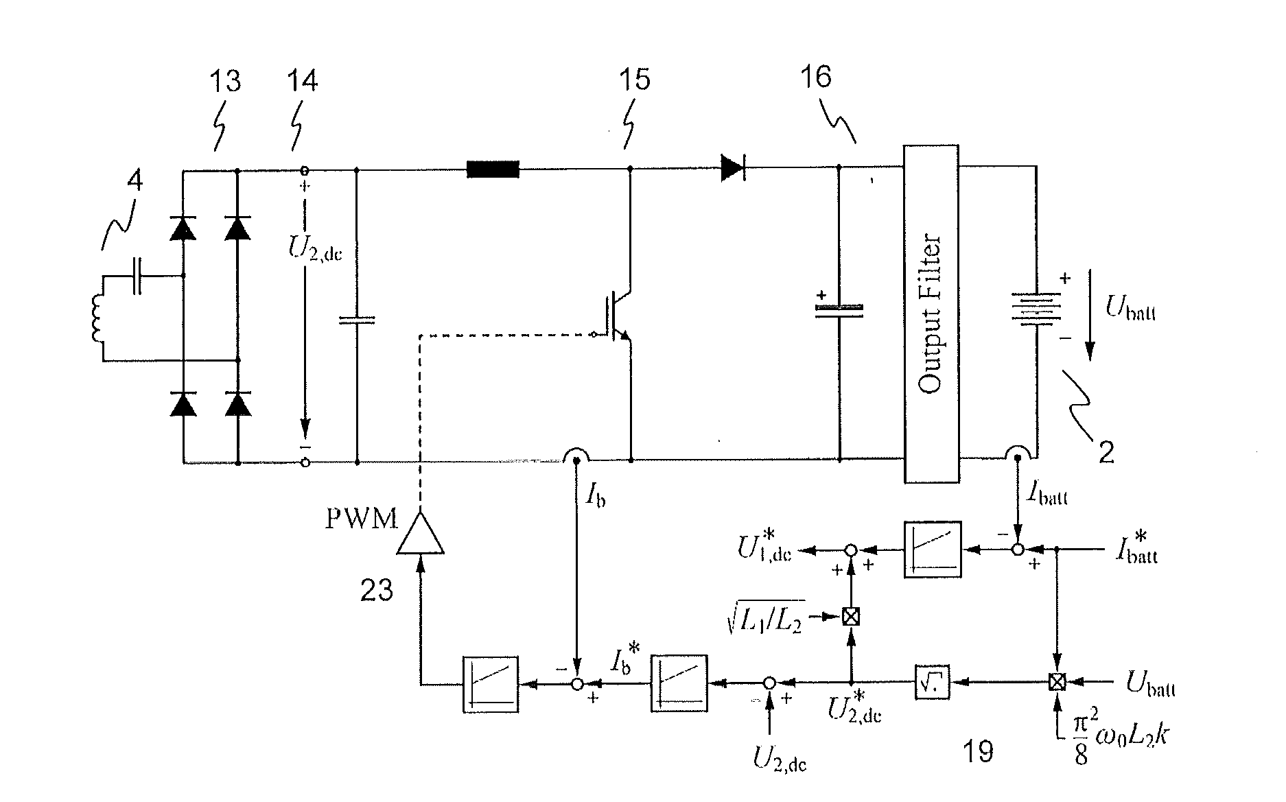
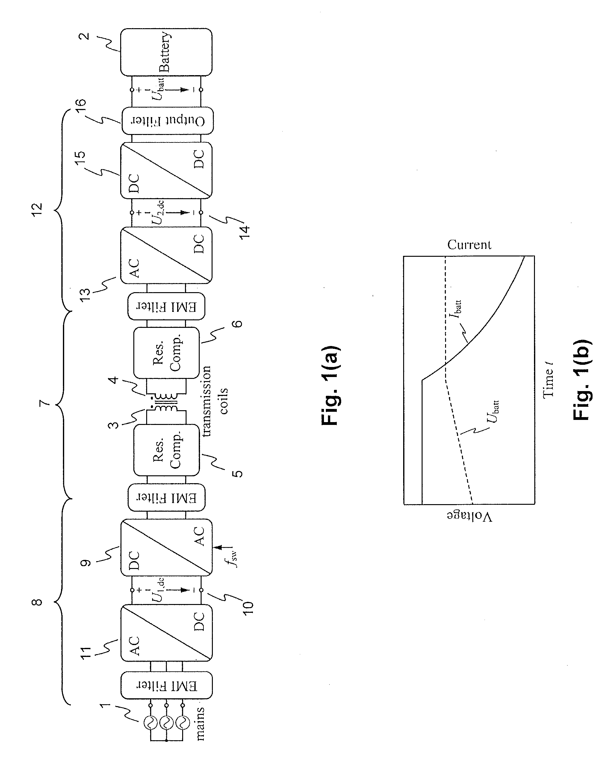
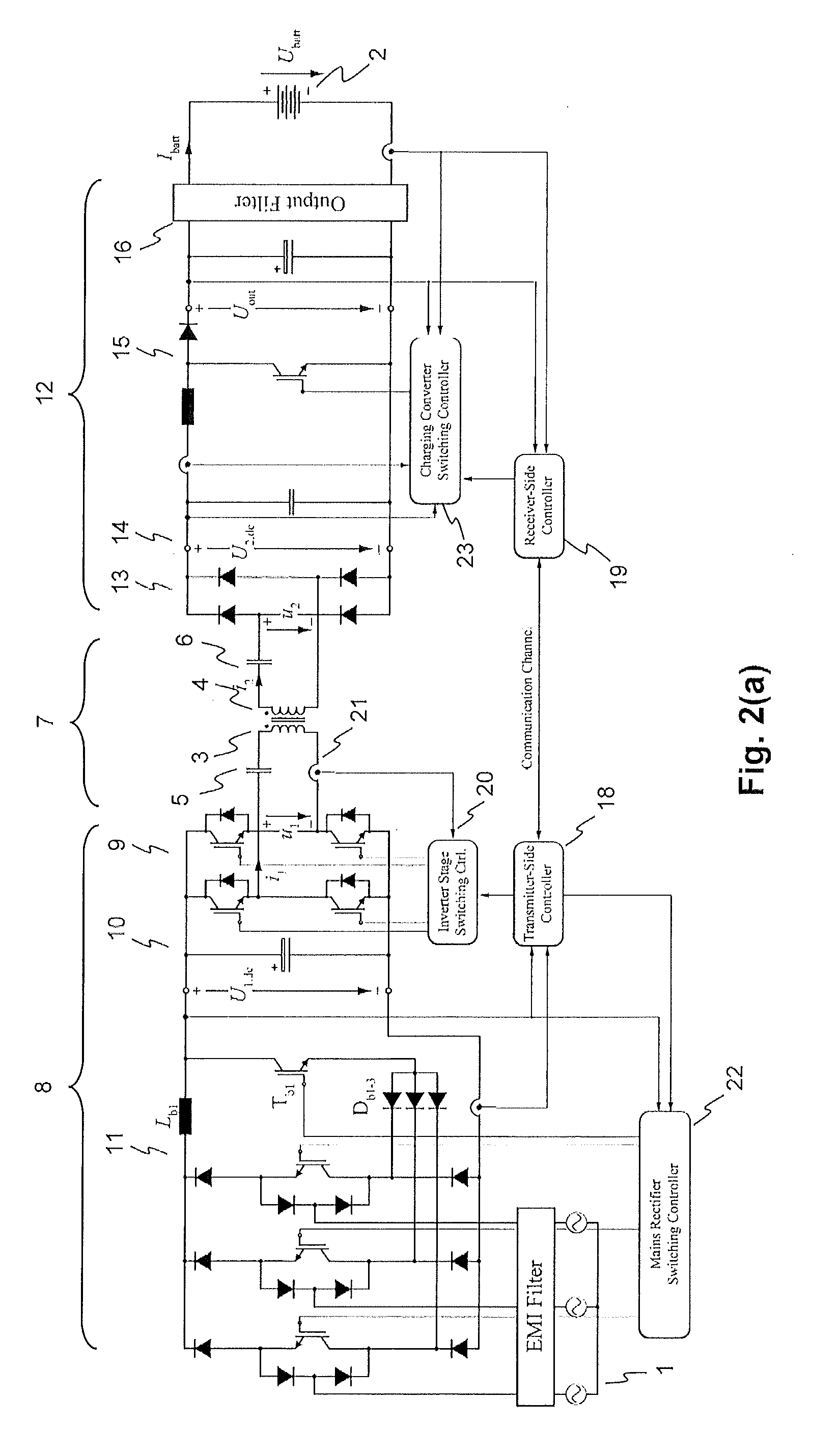
[0028]Exemplary embodiments of the present disclosure provide a power transfer system, such as an inductive charging system, and a control method that lead to a high efficiency of the power transfer charging process in a wide range of operating conditions, output power and—for a charging system—state-of-charge dependent battery voltage. Exemplary embodiments of the present disclosure provides an inductive charging system that exhibits a large tolerance to coil misalignment and a high robustness with respect to component tolerances and parameter drifts.

[0029]An exemplary embodiment of the present disclosure is directed to an inductive power transfer system, such as a battery charging system, for supplying electrical power from a transmitter-side subsystem connectable to a mains to a receiver-side subsystem connectable to a load. The system includes a transmitter coil and a receiver coil, a transmitter-side power converter having a mains rectifier stage to power a transmitter-side dc-...


PUM


Abstract

An exemplary inductive power transfer system having a transmitter coil and a receiver coil. A transmitter-side power converter having a mains rectifier stage powering a transmitter-side dc-bus and controlling a transmitter-side dc-bus voltage U1,dc. A transmitter-side inverter stage with a switching frequency fsw supplies the transmitter coil with an alternating current. A receiver-side power converter having a receiver-side rectifier stage that rectifies a voltage induced in the receiver coil and powering a receiver-side dc-bus and a receiver-side charging converter controlling a receiver-side dc-bus voltage U2,dc. Power controllers that determine from a power transfer efficiency of the power transfer, reference values U1,dc*, U2,dc* for the transmitter and receiver side dc-bus voltages. An inverter stage switching controller controls the switching frequency fsw to reduce losses in the transmitter-side inverter stage.

Description

RELATED APPLICATION(S)[0001]This application claims priority under 35 U.S.C. §119 to European application No. 14162789.3 filed in Europe on Mar. 31, 2014, the entire content of which is hereby incorporated by reference.FIELD[0002]The disclosure relates to an inductive power transfer system, in particular a battery charging system for the wireless transmission of charging energy to an electric vehicle and a method for operating such a power transfer or charging system.BACKGROUND INFORMATION[0003]Inductive charging systems designed for electric vehicles (EV) employ a transmitter coil, which is placed on or embedded in the road surface, to inductively transmit the charging energy via the air gap between the road surface and the vehicle to a receiver coil mounted to the underfloor of the EV. Similar to a traditional transformer, an alternating current in the windings of the transmitter coil is used to produce the magnetic flux specified to transfer the charging energy. Due to the large ...

Claims


Application Information

Patent Timeline
Patent Type & Authority Applications(United States)
IPC IPC(8): H02J5/00
CPCH02J5/005H02M3/3376B60L2210/10B60L2210/30B60L2210/40Y02T10/7072Y02T90/14B60L53/22B60L53/126B60L53/122H02J7/00712Y02T10/70Y02T10/72H02M1/0058H02M1/007H02J50/80H02J50/90H02J50/12B60L5/005Y02T90/12H02M1/0054
Inventor BOSSHARD, ROMANKOLAR, JOHANN WALTERCANALES, FRANCISCOGUGGISBERG, BEATGONG, GUANGHAIWUNSCH, BERNHARD
Owner ABB (SCHWEIZ) AG
Why Eureka
Try Eureka