Helmholtz type differential acoustic resonator detection device

a detection device and differential acoustic resonator technology, applied in semiconductor lasers, instruments, lasers, etc., can solve the problems of limited transmission wavelength, device limitation, and limited non-miniaturised laboratory devices

Active Publication Date: 2015-10-08
COMMISSARIAT A LENERGIE ATOMIQUE ET AUX ENERGIES ALTERNATIVES
View PDF1 Cites 12 Cited by
  • Summary
  • Abstract
  • Description
  • Claims
  • Application Information

AI Technical Summary

Problems solved by technology

Such devices nevertheless have the drawbacks of being limited to non-miniaturised laboratory devices, of having limited transmission wavelengths, of being sensitive to temperature variations and to vibrations, and of having considerable constraints of positioning and alignment of their elements to produce them.
The miniaturisation and the integration on silicon of this type of detector nevertheless pose a problem.
At the inlet of the excited chamber, the beam undergoes a diffra

Method used


Image

  • Helmholtz type differential acoustic resonator detection device
  • Helmholtz type differential acoustic resonator detection device
  • Helmholtz type differential acoustic resonator detection device

Examples


Embodiment Construction

[0011]Thus there is a need to propose a DHR integrated type of photoacoustic detection device, and in which the confinement of the light beam intended to be injected into one of the chambers of the device is improved.

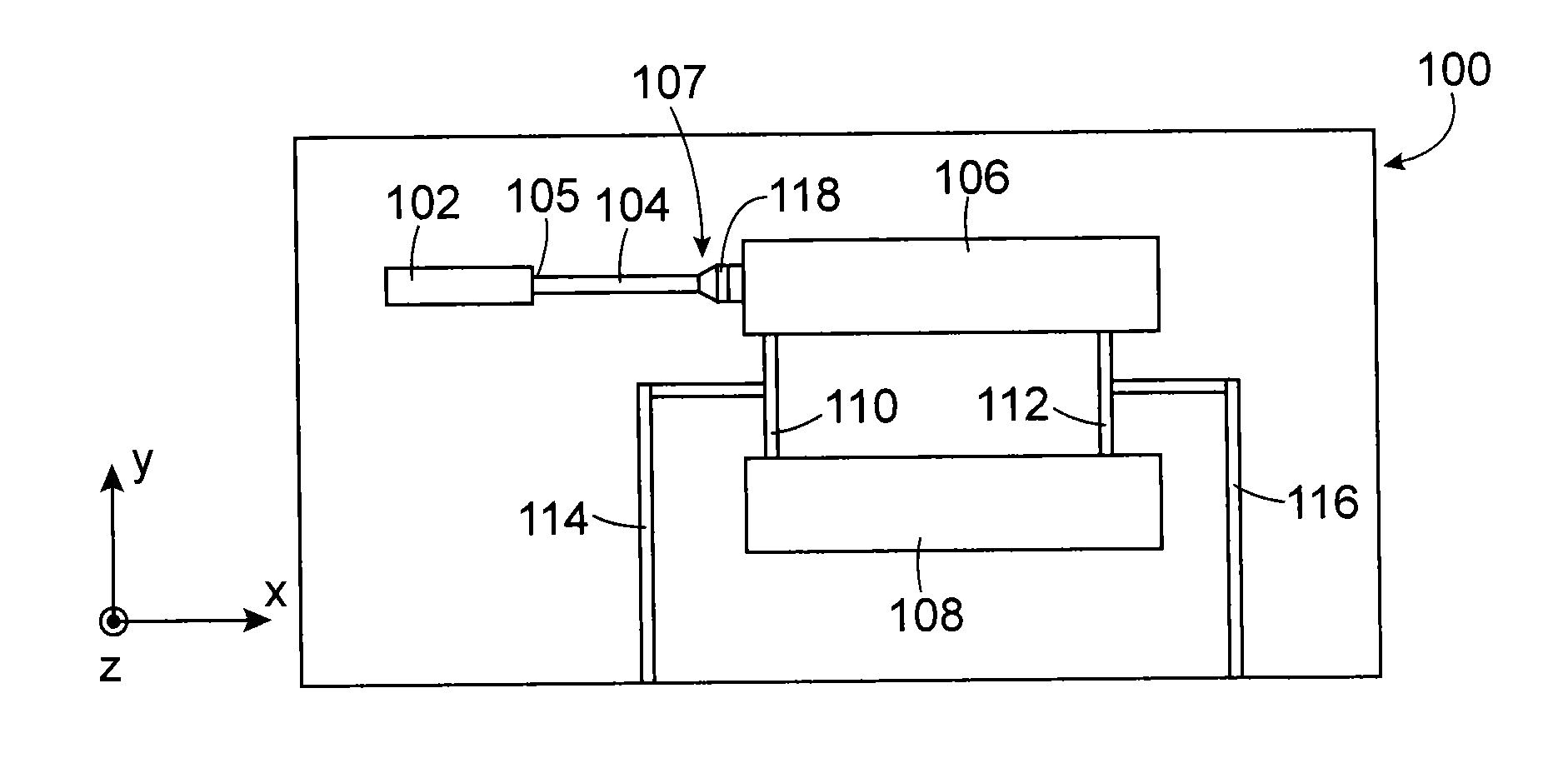
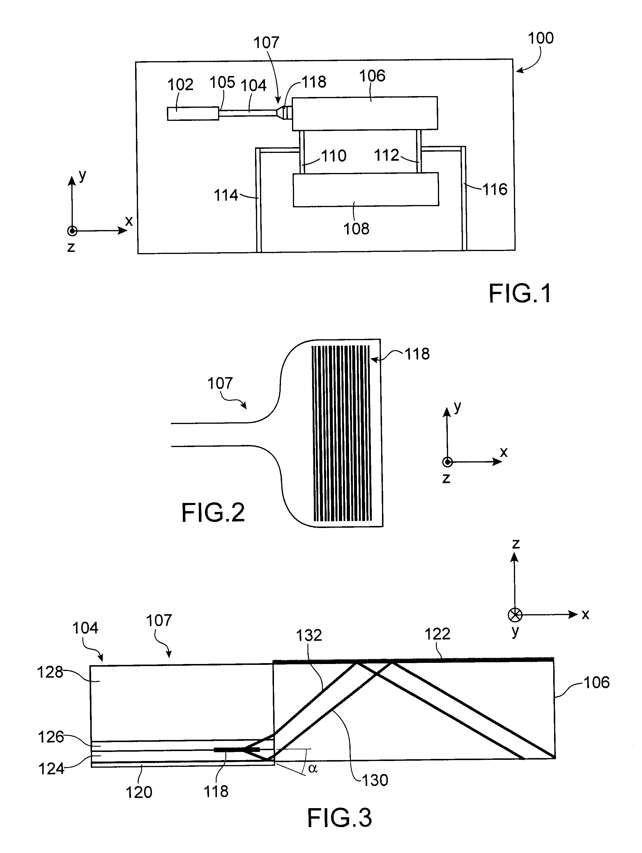
[0012]To achieve this, one embodiment proposes a photoacoustic detection device comprising:[0013]at least one substrate comprising cavities forming a Helmholtz type differential acoustic resonator (or DHR);[0014]acoustic detectors coupled to two of said cavities forming chambers of the resonator;[0015]a light source capable of emitting a light beam at at least one given wavelength;[0016]an optical waveguide comprising a first end optically coupled to the light source and a second end optically coupled to a first of the two chambers;

[0017]in which the second end comprises, at an interface with the first chamber, a width of value greater than that of the width of the first end and greater than that of said at least one given wavelength, and / or in which the photoacoustic d...


PUM


Abstract

Microelectronic photoacoustic detection device comprising:
    • a substrate comprising cavities forming a Helmholtz differential acoustic resonator;
    • acoustic detectors coupled to the chambers of the resonator;
    • a light source;
    • a waveguide comprising a first end coupled to the light source and a second end coupled to a first chamber;
    • in which the second end comprises, at the interface with the first chamber, a width greater than that of the first end and that of the given wavelength, and/or in which the device comprises a diffraction grating arranged in the second end and capable of diffracting a first part of the beam towards a lower reflective layer arranged under the second end and a second part of the beam towards an upper reflective layer arranged at an upper wall of the first chamber.

Description

TECHNICAL FIELD AND PRIOR ART[0001]The invention relates to the field of photoacoustic detection devices, and especially that of integrated gas sensors making use of a photoacoustic effect to measure the concentration of some gaseous elements.[0002]The principle of measuring a gas by photoacoustic effect is based on the excitation of an acoustic wave in the gas by a powerful light source such as a pulsed or amplitude or wavelength modulated laser. The wavelength of the mid-infrared radiation (MIR) emitted by the laser is chosen to interact with the molecules of the gas to be detected. Since the emission of the light source is variable over time, the energy absorbed by the gaseous molecules is restored in the form of a transitory heating which generates a pressure wave, itself measured by an acoustic detector.[0003]Detection is improved by confining the gas in a cavity and by modulating the laser to an acoustic resonance frequency of the cavity. The amplitude of the acoustic wave obt...

Claims


Application Information

Patent Timeline
IPC IPC(8): G01N21/3504H01S5/026G01N21/03
CPCG01N21/3504G01N21/03G01N2201/08G01N2201/0612H01S5/026G01N29/036G01N29/222G01N29/2425G01N21/1702G01N2021/1704G01N2021/1708G01N2291/021G01N2201/06113G01N21/0303
Inventor GLIERE, ALAINBOUTAMI, SALIMBRUN, MICKAELLABEYE, PIERRENICOLETTI, SERGIOROUXEL, JUSTIN
Owner COMMISSARIAT A LENERGIE ATOMIQUE ET AUX ENERGIES ALTERNATIVES
Why Eureka
Try Eureka