Interference cancellation method, system, device and ue

a technology of interference cancellation and system, applied in the field of interference cancellation techniques in wireless communications, can solve the problems of poor continuous splitting potential, serious inter-cell interference, and uneven distribution of users in space, and achieve the effects of improving the throughput of cellular networks, and facilitating demodulation and cancellation

Active Publication Date: 2015-10-15
SAMSUNG ELECTRONICS CO LTD
View PDF8 Cites 7 Cited by
  • Summary
  • Abstract
  • Description
  • Claims
  • Application Information

AI Technical Summary

Benefits of technology

[0012]In view of above, examples of the present application provide an interference cancellation method, which can deal with the inter-cell interference better and improve the throughput of cellular networks.
[0013]Examples of the present application further provide an interference cancellation system, device and an UE, which can deal with the inter-cell interference better and improve the throughput of cellular networks.
[0014]As can be seen from above mentioned technical solutions, in the present application, two base stations, by coordinating transmission modes of associated UEs, can control the impact of inter-cell interference so that the interference can be more easily demodulated and canceled, thereby enhancing the total data rate of two users, and improving the network throughput.

Problems solved by technology

However, the cell radius in the fourth generation mobile communication (4G) system has been relatively small, and the potentiality for continuous splitting is poor.
In addition, the distribution of users in space is not uniform, and a large number of users in a cell may locate in some hot spots and occasions.
In a homogeneous network, inter-cell interference is serious only at the edge of a cell.
The power of a macro base station differs considerably from that of a micro base station, which results in asymmetric downlink.

Method used


Image

  • Interference cancellation method, system, device and ue
  • Interference cancellation method, system, device and ue
  • Interference cancellation method, system, device and ue

Examples


first example

The First Example

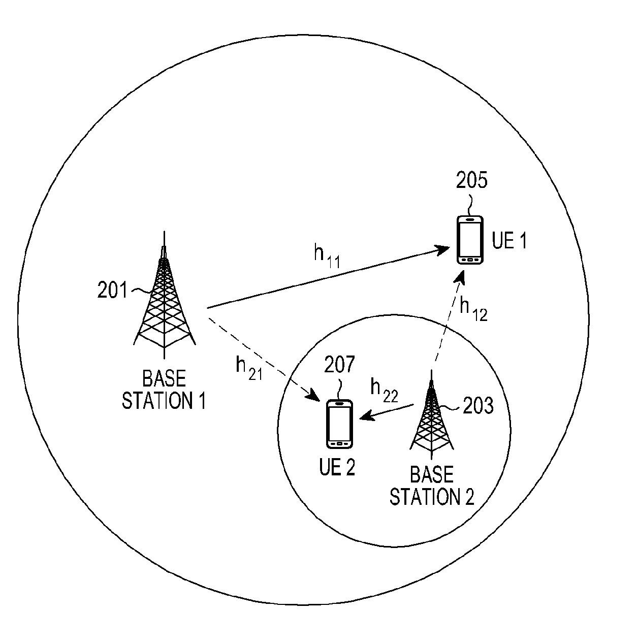
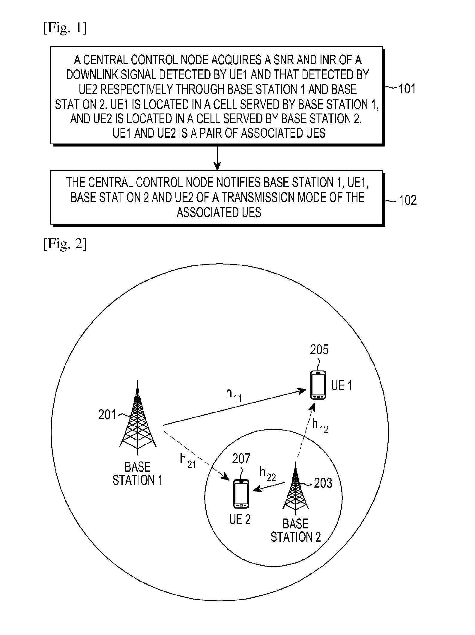
[0040]FIG. 2 is a schematic diagram illustrating system environment according to the first example of the present application.

[0041]System environment of the first example of the present application is shown in FIG. 2. A macro base station BS1(201) and a micro base station BS2(203) are deployed in a circular region. The two base stations are connected to each other and interact information via a backbone network. A central control node (not shown) may be set in the macro base station BS1(201).

[0042]The central control node selects a UE, i.e. UE1(205), from a macro cell served by the macro base station BS1(201), and selects another UE, i.e. UE2(207), from a micro cell served by the micro base station BS2(203), and takes the two selected UEs(205, 207) as a pair of associated UEs. In general, the number of UEs in a micro cell is far less than the number of UEs in a macro cell, so it is possible to determine a UE in the micro cell first, and then determine a UE in the m...

second example

The Second Example

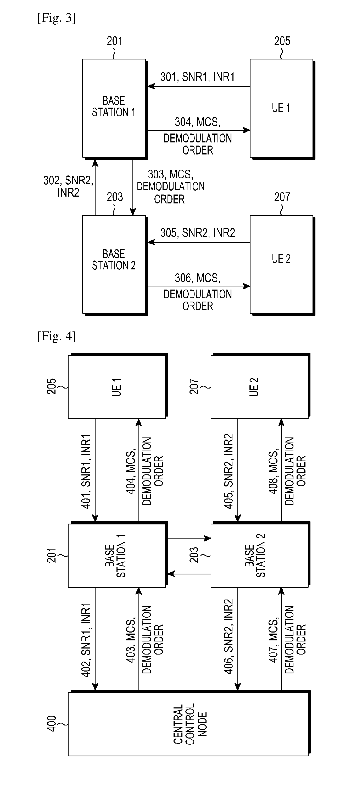
[0069]FIG. 4 is a schematic diagram illustrating signaling interaction according to the second example of the present application.

[0070]In this example, suppose there is a stand-alone central control node(400) in the system, then BS1(201) and BS2(203) report channel measurement information, namely SNR1, INR1, SNR2 and INR2, to the central control node(400).

[0071]After calculating the MCSs and demodulation orders of the two UEs, the central control node(400) sends the calculated transmission mode information to BS1(201) and BS2(203), and then BS1(201) and BS2(203) respectively forward the transmission mode information to UE1(205) and UE2(207). In this case, the signaling interaction of the whole process is shown in FIG. 4, which includes the following.

[0072]Flow 401, UE1(205) sends the values of detected SNR and INR, namely SNR1 and INR1 to BS1(201).

[0073]Flow 405, UE2(207) sends the values of detected SNR and INR, namely SNR2 and INR2 to BS2(203).

[0074]Flow 402, BS...


PUM


Abstract

Examples of the present application provide an interference cancellation method, system, device and a UE. The interference cancellation method of a communication network including a plurality of User Equipments (UEs) and Base Stations (BSs) includes: acquiring a Signal to Noise Ratio (SNR) and Interference to Noise Ratio (INR) of a downlink signal detected by a first UE and a SNR and INR of a downlink signal detected by a second UE, respectively through a first BS and a second BS; and notifying the first BS and the second BS of a transmission mode of associated UEs, wherein the first UE is located in a cell served by the first BS, and the second UE is located in a cell served by the second BS.

Description

TECHNICAL FIELD[0001]The present application relates to interference cancellation techniques in wireless communications, and more particularly, to an interference cancellation method, system, device and a User Equipment (UE).BACKGROUND ART[0002]The design of cellular systems has evolved to pursue the spatial capacity from simply pursuing the spectrum efficiency. Cell splitting is a common method to improve the spatial reuse efficiency of the spectrum. However, the cell radius in the fourth generation mobile communication (4G) system has been relatively small, and the potentiality for continuous splitting is poor. In addition, the distribution of users in space is not uniform, and a large number of users in a cell may locate in some hot spots and occasions. A heterogeneous network is more suitable for this scenario of uneven user distribution. The basic ideas of the heterogeneous network are as follows. A macro base station transmitting with larger power seamlessly covers a macro cel...

Claims


Application Information

Patent Timeline
Patent Type & Authority Applications(United States)
IPC IPC(8): H04W52/24H04B17/345H04L1/00H04B15/02
CPCH04W52/241H04B15/02H04L1/0003H04L1/00H04W52/244H04B17/345H04W52/243H04W84/045H04W92/20
Inventor SUN, CHENGJUNYANG, CHENYANGTIAN, YAFEILI, YINGYANG
Owner SAMSUNG ELECTRONICS CO LTD
Why Eureka
Try Eureka