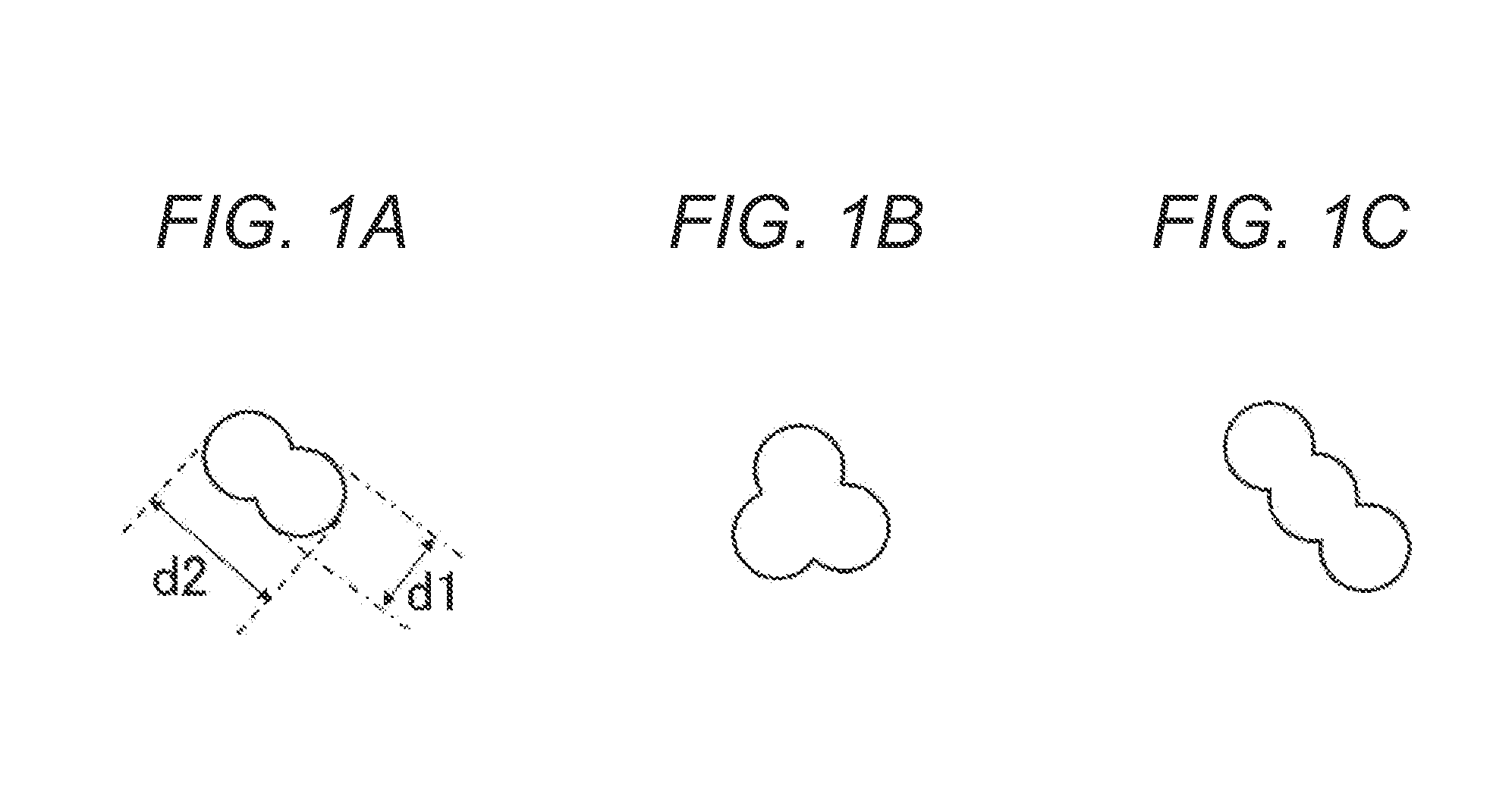
Electrostatic charge image developing toner
a charge image and developing toner technology, applied in the field of electrostatic charge image developing toner, can solve the problems of not being able to provide charge stability and cannot be prevented from transferring to the carrier, and achieve the effect of high charge stability and less likely to undergo durability degradation
- Summary
- Abstract
- Description
- Claims
- Application Information
AI Technical Summary
Benefits of technology
Problems solved by technology
Method used
Image
Examples
production example 4
for Toner Matrix Particles
[0197]Toner matrix particles [4] were prepared as in Production Example 1 for toner matrix particles, except that a dispersion [1] of polyester resin fine particles prepared as described below was used instead of the dispersion [1] of styrene acrylic resin fine particles in (3) preparation of toner matrix particles.
[0198]Preparation of dispersion of Polyester Resin Fine Particles
[0199](1) Synthesis of Polyester Resin
[0200]Three hundred sixty parts by mass of a 2-mole propylene oxide adduct of bisphenol A, 80 parts by mass of terephthalic acid, 55 parts by mass of fumaric acid, and 2 parts by mass of titanium tetraisopropoxide as a polycondensation catalyst were added in 10 parts to a reaction chamber equipped with a condenser tube, a stirrer, and a nitrogen introducing tube. The mixture was allowed to react at 200° C. for 10 hours under a nitrogen stream while the produced water was removed by distillation. The reaction mixture was then allowed to react at ...
production example 5
for Toner Matrix Particles
[0203]Toner matrix particles [5] were prepared as in Production Example 1 for toner matrix particles, except that (3) preparation of toner matrix particles was performed as described below.
[0204]Preparation of Toner Matrix Particles
[0205]A reaction vessel equipped with a stirrer, a temperature sensor, and a condenser tube was charged with 300 parts by mass (on solid basis) of the dispersion [1] of styrene acrylic resin fine particles and 2,000 parts by mass of ion exchanged water. An aqueous 5 mol / liter sodium hydroxide solution was then added to adjust the pH of the mixture to 10. Subsequently, 40 parts by mass (on solid basis) of the dispersion [C] of colorant fine particles was added to the mixture. An aqueous solution prepared by dissolving 60 parts by mass of magnesium chloride in 60 parts by mass of ion exchanged water was then added over 10 minutes to the mixture at 30° C. under stirring. Subsequently, the mixture was allowed to stand for 3 minutes a...
production example 6
for Toner Matrix Particles
[0207]Toner matrix particles [6] were prepared as in Production Example 1 for toner matrix particles, except that a dispersion [1] of vinyl-modified polyester resin fine particles prepared as described below was used instead of the dispersion [1] of binder resin fine particles in (3) preparation of toner matrix particles.
[0208]Preparation of Dispersion of Vinyl-Modified Polyester Resin Fine Particles
[0209](1) Synthesis of Vinyl-Modified Polyester Resin
[0210]A 10-liter-volume, four-neck flask equipped with a nitrogen introducing tube, a dewatering tube, a stirrer, and a thermocouple was charged with 480 parts by mass of a 2-mole propylene oxide adduct of bisphenol A, 130 parts by mass of terephthalic acid, 85 parts by mass of fumaric acid, and 2 parts by mass of an esterification catalyst (tin octoate). The mixture was subjected to a polycondensation reaction at 230° C. for 8 hours and then further allowed to react at 8 kPa for 1 hour. After the reaction mix...
PUM
| Property | Measurement | Unit |
|---|---|---|
| particle size d2 | aaaaa | aaaaa |
| diameter | aaaaa | aaaaa |
| acid value | aaaaa | aaaaa |
Abstract
Description
Claims
Application Information
 - R&D
- Intellectual Property
- Life Sciences
- Materials
- Tech Scout
- Unparalleled Data Quality
- Higher Quality Content
- 60% Fewer Hallucinations
Browse by: Latest US Patents, China's latest patents, Technical Efficacy Thesaurus, Application Domain, Technology Topic, Popular Technical Reports.
© 2025 PatSnap. All rights reserved.Legal|Privacy policy|Modern Slavery Act Transparency Statement|Sitemap|About US| Contact US: help@patsnap.com

