Plasma reactor for abatement of hazardous material

a plasma reactor and hazardous material technology, applied in the field of plasma reactors, can solve the problems of reducing the decomposition rate of hazardous materials passing through the center area of the plasma reactor, deteriorating the durability of vacuum pumps, and undecomposed precursors accumulated between vacuum pumps and scrubbers, so as to reduce the dependence of hazardous materials, increase the decomposition rate of hazardous materials, and good decomposition performan

Active Publication Date: 2015-11-05
KOREA INST OF MACHINERY & MATERIALS
View PDF0 Cites 21 Cited by
  • Summary
  • Abstract
  • Description
  • Claims
  • Application Information

AI Technical Summary

Benefits of technology

[0012]The present invention relates to a plasma reactor for decomposing and removing various hazardous materials in a front part of a vacuum pump, and to provide a plasma reactor for use of abating hazardous materials that allows the hazardous materials to be effectively decomposed and removed even in a large range of pressure condition by increasing the decomposition rate of hazardous materials when the pressure changes.
[0013]In addition, the present invention is to provide a plasma reactor for the use of removing hazardous materials that may increase the decomposition rate of greenhouse gases while guaranteeing safety of process without using water vapor, and simplifies the entire system since it does not require additional equipment such as a bubbler.
[0024]While passing through the upper to the center area of the plasma reactor, undecomposed hazardous materials are completely decomposed and removed by the plasma that is powerfully formed around the sheath region by passing through the sheath region over the facing part. Therefore, it is possible to increase the decomposition rate of hazardous materials in the high pressure and to decrease the dependence of the hazardous materials on pressure so that it may allow good decomposition performance in a larger pressure range.
[0025]Also, the plasma reactor is separately equipped with a source of oxygen and a source of hydrogen (or hydrocarbon), and by injecting while dividing two kinds of reaction gases through two inlets, the decomposition rate of hazardous substances included in the process gases can be effectively improved compared with the conventional art in which water vapor (H2O) is used as a reaction gas. Additionally, safety during the process is secured owing to avoiding the explosion by setting a time difference in the dissociation of oxygen and hydrogen (or hydrocarbon).

Problems solved by technology

Restrictions on emissions of the greenhouse gases that cause global warming have been tightened, and the particle by-products deteriorate the durability of vacuum pump while being accumulated in the vacuum pump.
As a result, this may cause an explosion due to being excessively expanded while expansion and shrinking is repeated.
In addition, the undecomposed precursor accumulated between the vacuum pump and the scrubber is exposed when replacing the vacuum pump, the scrubber, or pipe, and some of this may cause a fire while violently reacting with air.
However, in a mere pipe-shaped plasma reaction, it has been reported that the decomposition rate of the hazardous materials passing through the center area of a plasma reactor is decreased as the pressure is increased, which may cause a problem that the decomposition rate of the hazardous materials is decreased when the pressure is changed.
However, although the method of inputting the water vapor is good in terms of safety of the process, it has drawbacks that the decomposition rate of the greenhouse gases is low and the amounts of oxygen and hydrogen are unable to be individually controlled.
In addition, there is a technical difficulty in finely controlling the input of water vapor, and there is a limit that the entire system becomes complex since additional equipment such as a bubbler are required.

Method used


Image

  • Plasma reactor for abatement of hazardous material
  • Plasma reactor for abatement of hazardous material
  • Plasma reactor for abatement of hazardous material

Examples


Embodiment Construction

[0042]Hereinafter, the exemplary embodiments of the present invention will be described more fully with reference to the accompanying drawings so that those skilled in the art would easily utilize it. The present invention may be implemented in various forms, and the scope of the present invention is not limited to the embodiments described herein.

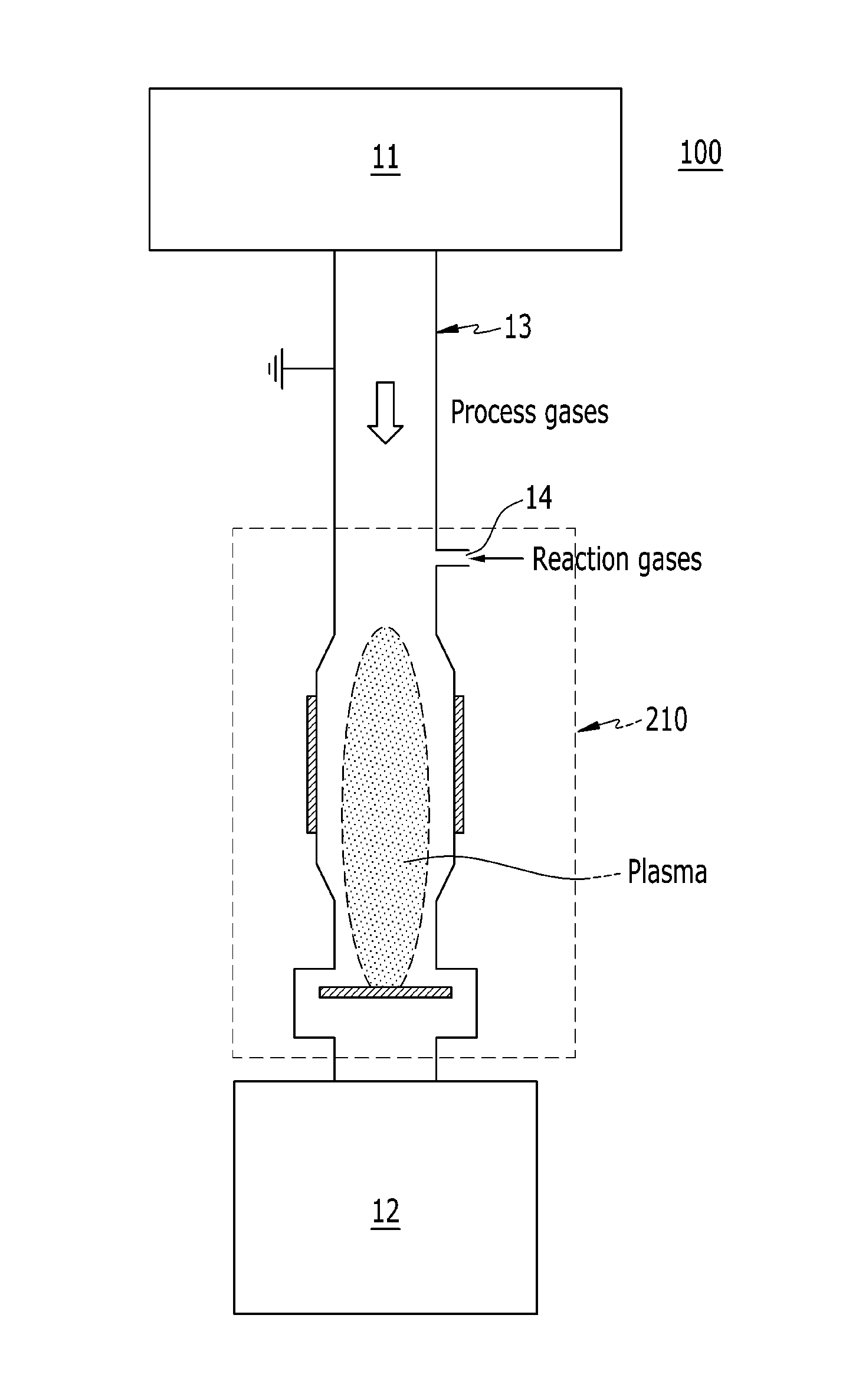
[0043]FIG. 1 is a schematic diagram of a process system including a plasma reactor according to the first exemplary embodiment of the present invention. The process system of FIG. 1 may be a low pressure process system for semiconductors, displays, solar cells, and so on.

[0044]Referring to FIG. 1, a process system 100 includes a process chamber 11 in which tasks such as etching, deposition, cleaning, etc. are processed, a vacuum pump 12 that is connected to the process chamber through a pipe 13 and releases process gases used in the process chamber 11, and a plasma reactor 210 that is installed between the process chamber 11 and the vacuum...


PUM

PropertyMeasurementUnit
pressureaaaaaaaaaa
pressureaaaaaaaaaa
diameteraaaaaaaaaa

Abstract

A plasma reactor for abating hazardous materials included in process gases while being installed on an exhaust path of the process gases toward a vacuum pump is provided. The plasma reactor includes an insulator having a pipe shape through which process gases pass, a first ground electrode connected to a front end of the insulator facing the process chamber, a second ground electrode connected to a rear end of the insulator and provided with a facing part that faces a center of the inside of the insulator along the moving direction of process gases, and a driving electrode fixed to an external circumferential surface of the insulator and connected to a power supply applying an AC or RF voltage.

Description

CROSS-REFERENCE TO RELATED APPLICATION[0001]This application claims priority to and the benefit of Korean Patent Application No. 10-2014-0052436 and 10-2014-0083093 filed in the Korean Intellectual Property Office on Apr. 30, 2014 and Jul. 3, 2014, the entire contents of which are incorporated herein by reference.BACKGROUND OF THE INVENTION[0002]1. (a) Field of the Invention[0003]The present invention relates to a plasma reactor, and more particularly, to plasma reactor for attaining an environmentally friendly process by decomposing and removing various hazardous materials caused by a process chamber in a front part of a vacuum pump.[0004]2. (b) Description of the Related Art[0005]A process chamber for performing processes such as etching, deposition, cleaning, and so on is installed in a manufacturing line of a semiconductor, a display, a solar cell, and the like, and the process chamber is connected to a vacuum pump to evacuate process gases. Various hazardous materials are disch...

Claims


Application Information

Patent Timeline
Patent Type & Authority Applications(United States)
IPC IPC(8): B01D53/32
CPCB01D2259/818B01D53/32H01J37/32091H01J37/32834H05H1/46Y02C20/30H01J37/32844Y02P70/50H05H1/4652H05H2245/17
Inventor HUR, MINKANG, WOO SEOKLEE, JAE OK
Owner KOREA INST OF MACHINERY & MATERIALS
Why Eureka
Try Eureka