Liquefied gas processing system for ship

a technology for processing systems and liquefied gas, which is applied in the direction of marine propulsion, container discharging methods, vessel construction, etc., can solve the problems of large amount of power consumption, complex control of the entire system, and high initial installation cost, and achieves high initial installation cost, and efficient use

Inactive Publication Date: 2015-11-05
DAEWOO SHIPBUILDING & MARINE ENG CO LTD
View PDF1 Cites 29 Cited by
  • Summary
  • Abstract
  • Description
  • Claims
  • Application Information

AI Technical Summary

Benefits of technology

[0063]As described above, embodiments of the present invention provides a system for processing liquefied gas for a vessel that can supply liquefied gas stored in a storage tank and boil-off gas evaporating from the liquefied gas as fuel to an engine mounted to a vessel, thereby efficiently using the liquefied gas and the boil-off gas.
[0064]In addition, embodiments of the present invention provides a system for processing liquefied gas for a vessel that can gasify liquefied gas, stored in a storage tank, after compression by a pump and supply the liquefied gas to an engine, and compress boil-off gas, evaporating from the liquefied gas, with a compressor after discharge from the storage tank to supply the boil-off gas to the engine.
[0065]Further, embodiments of the present invention provides a system for processing liquefied gas for a vessel that can compress boil-off gas (BOG) discharged from a storage tank, supply some of the compressed BOG as fuel to an engine of a vessel, for example a propulsion system, and liquefy the rest of the compressed BOG by cold heat of BOG, newly discharged from the storage tank and not yet compressed, to return the rest of the compressed BOG to the storage tank.
[0066]Thus, according to the embodiments of the invention, the system for processing liquefied gas can re-liquefy BOG generated from a storage tank without a re-liquefaction apparatus requiring much energy consumption and excessive initial installation cost, thereby reducing energy consumption in the re-liquefaction apparatus.
[0067]In addition, according to the embodiments of the invention, the system for processing liquefied gas can use all BOG, generated during transportation of cargo (i.e. LNG) by an LNG carrier, as fuel of an engine, or store it again in a cargo tank through re-liquefaction, thereby reducing BOG wasted by a GCU or the like, and processing BOG through re-liquefaction without using a separate refrigerant such as nitrogen or the like.
[0068]Further, according to the embodiments of the invention, the system for processing liquefied gas does not require a re-liquefaction apparatus using a separate refrigerant (i.e. a nitrogen-refrigerant refrigeration cycle or a mixed-refrigerant refrigeration cycle) so that it is unnecessary to additionally install facilities for supplying and storing a refrigerant, thereby reducing initial installation and operation costs for the entire system.

Problems solved by technology

The generated boil-off gas (BOG) can increase the internal pressure of the storage tank and accelerate the flow of the liquefied gas due to the rocking of the vessel, causing structural problems.
Therefore, there is a problem in that the BOG must be burnt in a gas combustion unit (GCU) or must be discharged to the air when requisite fuel for an engine is less than the generated BOG.
In the case of a typical LNG carrier equipped with the re-liquefaction system and a low speed diesel engine, although BOG can be processed through the re-liquefaction system, control of the entire system is complicated and a considerable amount of power is consumed due to complexity in operation of the re-liquefaction system using nitrogen gas.

Method used


Image

  • Liquefied gas processing system for ship
  • Liquefied gas processing system for ship
  • Liquefied gas processing system for ship

Examples


embodiment 1

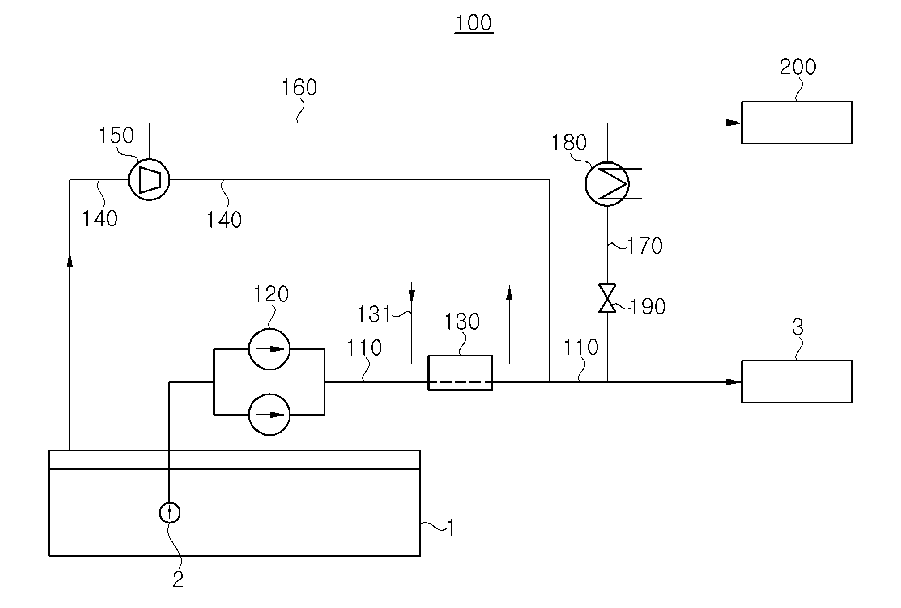
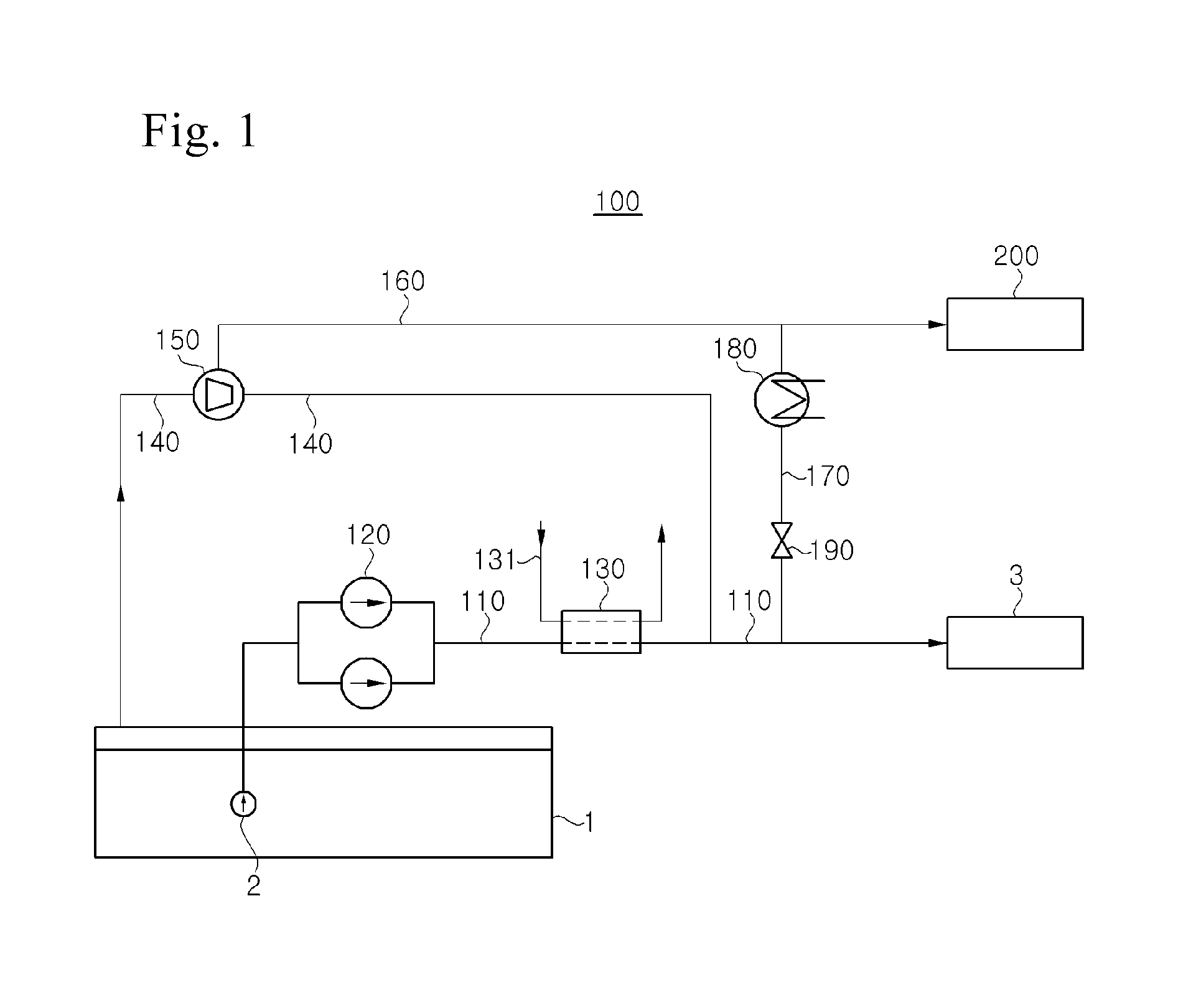
[0103]FIG. 1 is a configuration diagram of a liquefied gas processing system according to a first embodiment of the present invention. Referring to FIG. 1, a liquefied gas processing system 100 according to this embodiment includes a fuel supply line 110 configured to provide a path for delivering LNG from a storage tank 1 to a main engine 3 as a propulsion system, and a boil off gas (BOG) line 140 configured to provide a path for delivering BOG, generated from the storage tank 1, to the main engine 3. The liquefied gas processing system 100 using BOG according to this embodiment supplies LNG as fuel to the main engine 3 through the fuel supply line 110 by virtue of an LNG pump 120 and an LNG vaporizer 130, supplies BOG, compressed by a BOG compressor 150, as fuel to the main engine 3 through the BOG line 140, and supplies excess BOG from the BOG compressor 150 to an integrated IGG / GCU system 200.

[0104]A low-speed two-stroke low-pressure gas injection engine, used as the main engine...

embodiment 2

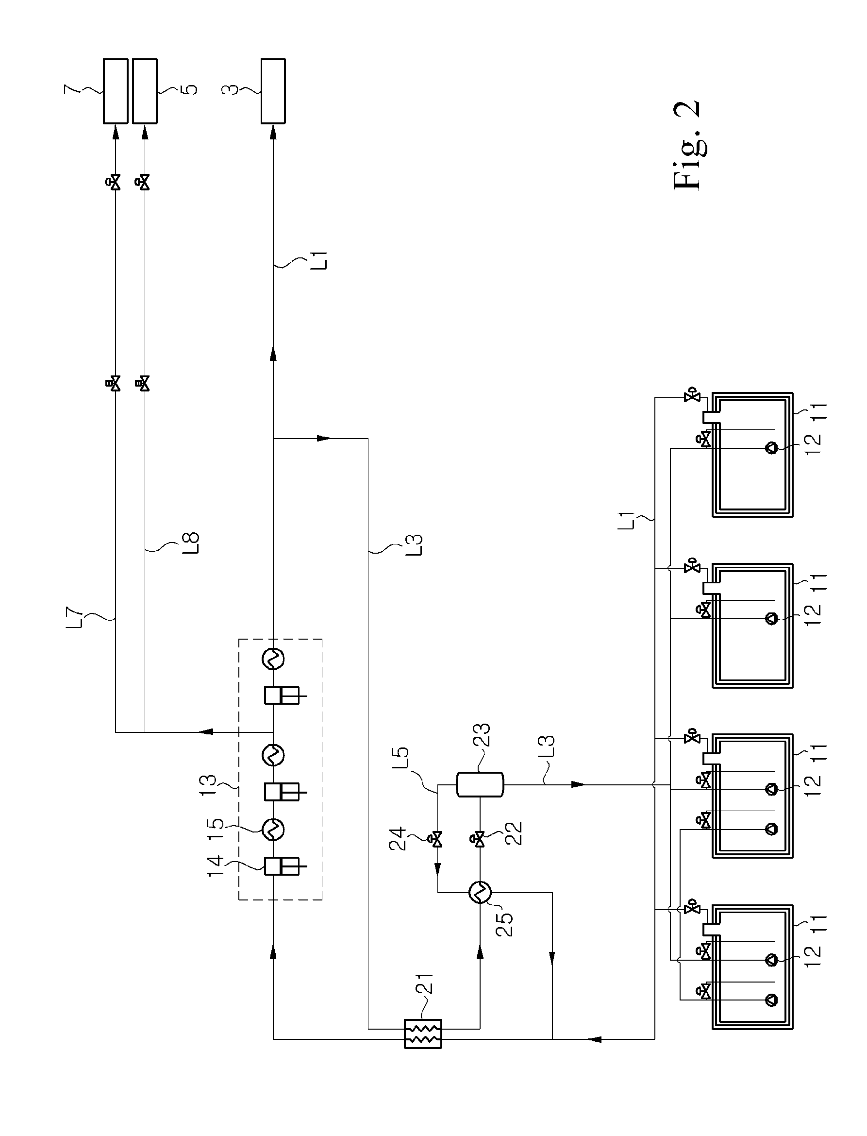
[0118]FIG. 2 is a schematic configuration diagram of a liquefied gas processing system for a vessel according to a second embodiment of the present invention.

[0119]In FIG. 2, the liquefied gas processing system according to this embodiment is employed for an LNG carrier equipped with an engine capable of using natural gas as fuel (i.e. a propulsion unit using LNG as fuel), for example, a low-speed two-stroke low-pressure gas injection engine. However, the liquefied gas processing system may be employed for all types of vessels equipped with a liquefied gas storage tank, such as an LNG carrier and an LNG re-gasification vessel (LNG RV), or offshore plants such as an LNG floating, production, storage and off-loading (LNG FPSO) unit, an LNG floating storage and re-gasification Unit (LNG FSRU), and a barge mounted power plant (BMPP).

[0120]In the liquefied gas processing system for the vessel according to the second embodiment of the invention, natural boil-off gas (NBOG) discharged from...

embodiment 3

[0141]FIG. 5 is a schematic configuration diagram of a liquefied gas processing system for a vessel according to a third embodiment of the present invention.

[0142]The liquefied gas processing system according to the third embodiment is different from that according to the second embodiment in that LNG may be used through forced gasification when requisite BOG for a main engine 3 or an auxiliary engine 5 is exceeds naturally generated BOG. Hereinafter, only the difference from the second embodiment will be described in more detail. In addition, like elements to those of the second embodiment are denoted by like numerals, and detailed descriptions thereof will be omitted.

[0143]The liquefied gas processing system for the vessel according to the third embodiment of the invention is similar to that according to the second embodiment in that NBOG, discharged from storage tanks 11 for storing liquefied gas, is delivered to a compressor 13 along a BOG supply line L1, compressed by the compr...


PUM


Abstract

Disclosed is a liquefied gas processing system for a ship that includes a storage tank that stores liquefied natural gas, and an engine that uses the liquefied natural gas stored in the storage tank as fuel. The liquefied gas processing system of the present invention comprises: a storage tank that stores liquefied gas; an engine that uses the liquefied gas stored in the storage tank as fuel; and a fuel supply line that can vaporize the liquefied gas and supply the generated gas to the engine as fuel. The engine receives a supply of the fuel gas that is pressurized at a low pressure.

Description

TECHNICAL FIELD[0001]The present invention relates to a system for processing liquefied gas for a vessel.BACKGROUND ART[0002]In recent years, the consumption of liquefied gas such as liquefied natural gas (LNG) or liquefied petroleum gas (LPG) has been rapidly increasing throughout the world. Liquefied gas is transported in a gaseous state through onshore or offshore gas pipelines, or transported to a remote consumption site while being stored in a liquefied state inside a liquefied gas carrier. Liquefied gas, such as LNG or LPG, is obtained by cooling natural gas or petroleum gas to cryogenic temperatures (in the case of LNG, about −163° C.). Since the volume of liquefied gas is considerably reduced as compared to a gaseous state, liquefied gas is suitable for long-distance marine transportation.[0003]A liquefied gas carrier is designed to load liquefied gas, sail across the sea, and unload the liquefied gas at an onshore consumption site. To this end, the liquefied gas carrier inc...

Claims


Application Information

Patent Timeline
Patent Type & Authority Applications(United States)
IPC IPC(8): F17C1/00
CPCF17C1/002B63H21/38F02M21/0287F17C13/00F17C2201/052F17C2221/033F17C2223/0161F17C2223/047F17C2227/0135F17C2227/0178F17C2265/034F17C2265/07F17C2270/0105F25J1/0025F25J1/004F25J1/0042F25J1/0202F25J1/0277F25J2240/40Y02E60/32Y02T10/30Y02T70/50Y02T70/5218Y02T90/40B63B25/16F02M21/02F25J1/00
Inventor BAE, JAE RYUCHOO, GYO SIGKIM, JIN KANGKIM, SUNG SOO
Owner DAEWOO SHIPBUILDING & MARINE ENG CO LTD
Why Eureka
Try Eureka