
Multi-source renewable energy station

a renewable energy and multi-source technology, applied in the integration of power network operation systems, transmission systems, position/direction control, etc., can solve the problems of inability to rely on renewable energy sources, inability to work with renewable energy sources, and intermittent renewable energy sources, etc., to achieve the effect of increasing the efficiency of solar panels

Inactive Publication Date: 2015-11-05
ILINCA ADRIAN +1
View PDF24 Cites 16 Cited by
  • Summary
  • Abstract
  • Description
  • Claims
  • Application Information

AI Technical Summary

Benefits of technology

The present invention provides a control system for a solar energy station that uses heat generated by a gas / diesel engine- generator during a maintenance run to remove ice formations on solar panels, thus increasing their efficiency. The system also includes controls to prioritize important loads during a shortage of available renewable power. The sources and loads are segmented and managed independently to reduce the risk of a low voltage or total loss of power. As soon as a low performance is detected on a generating cell, non-essential loads are disconnected and another generating cell is put on line to avoid an outage that can be detrimental to the station's vocation.

Problems solved by technology

Working with renewable energy sources, however, is not free of risks and challenges.
But most of all, renewable energy sources are intermittent and cannot be relied upon when the customer needs a stable and reliable electrical power supply.
The management of renewable energy sources requires relatively complex electronic equipment.

Method used


Image

  • Multi-source renewable energy station
  • Multi-source renewable energy station
  • Multi-source renewable energy station

Examples


Embodiment Construction

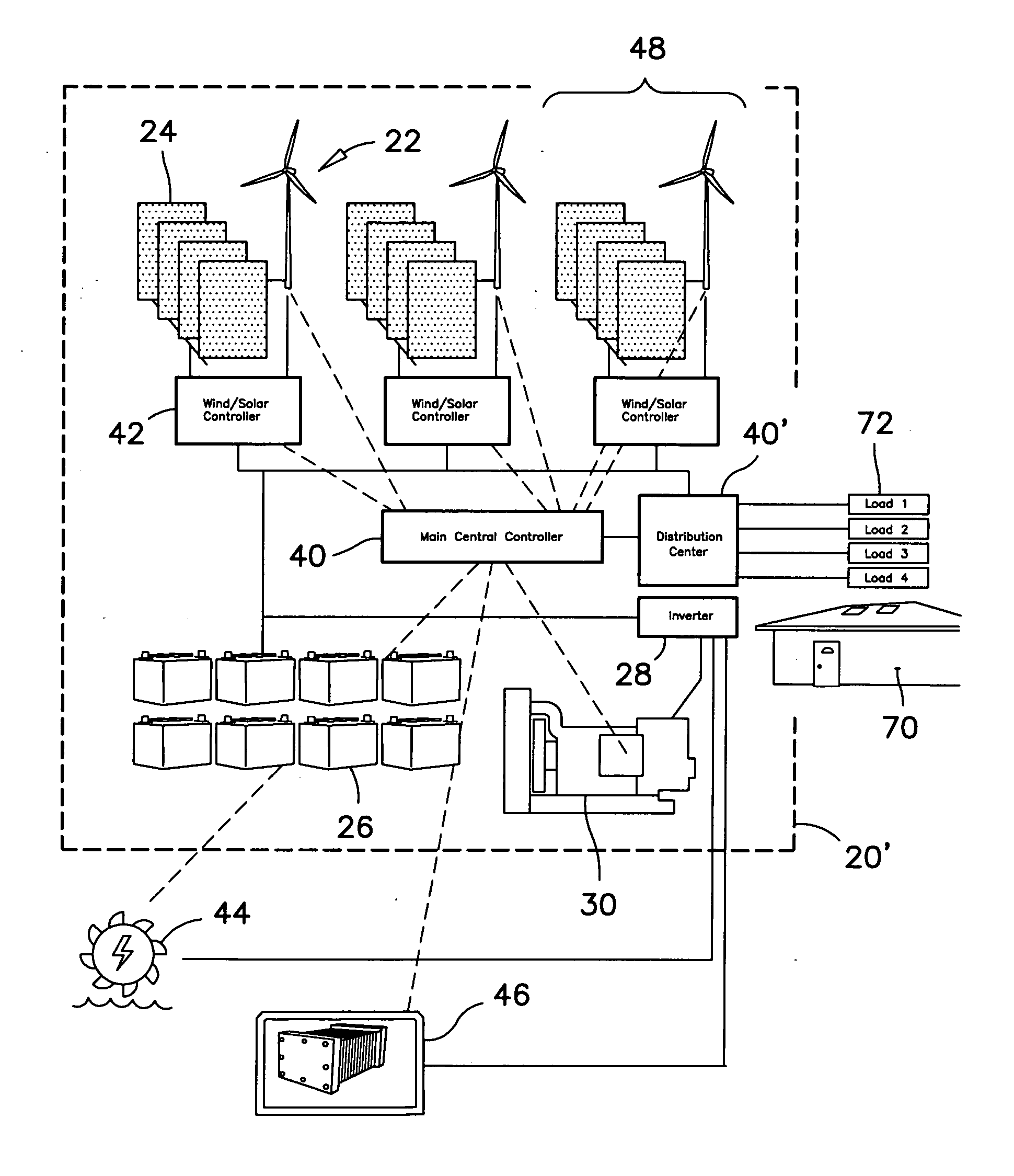
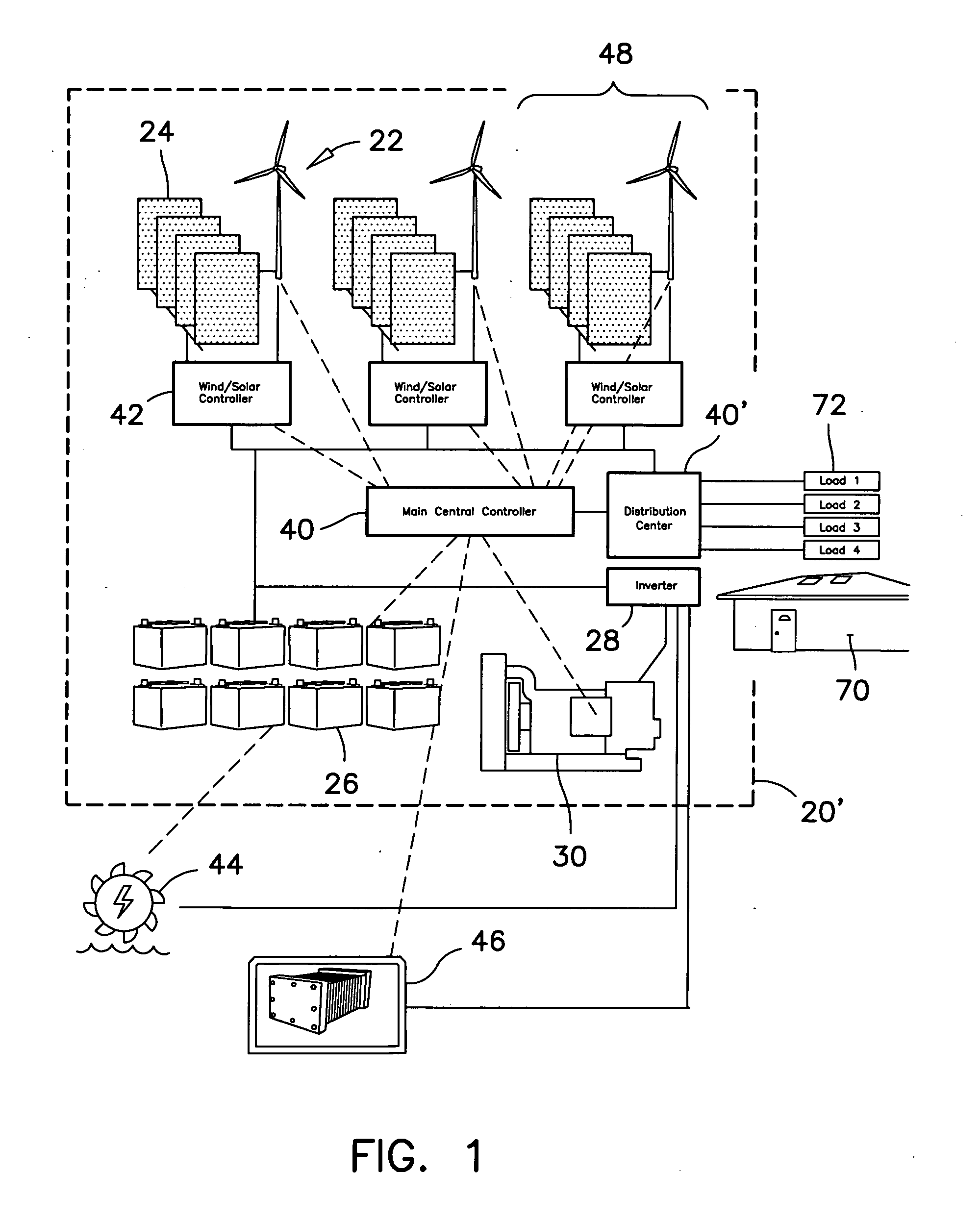
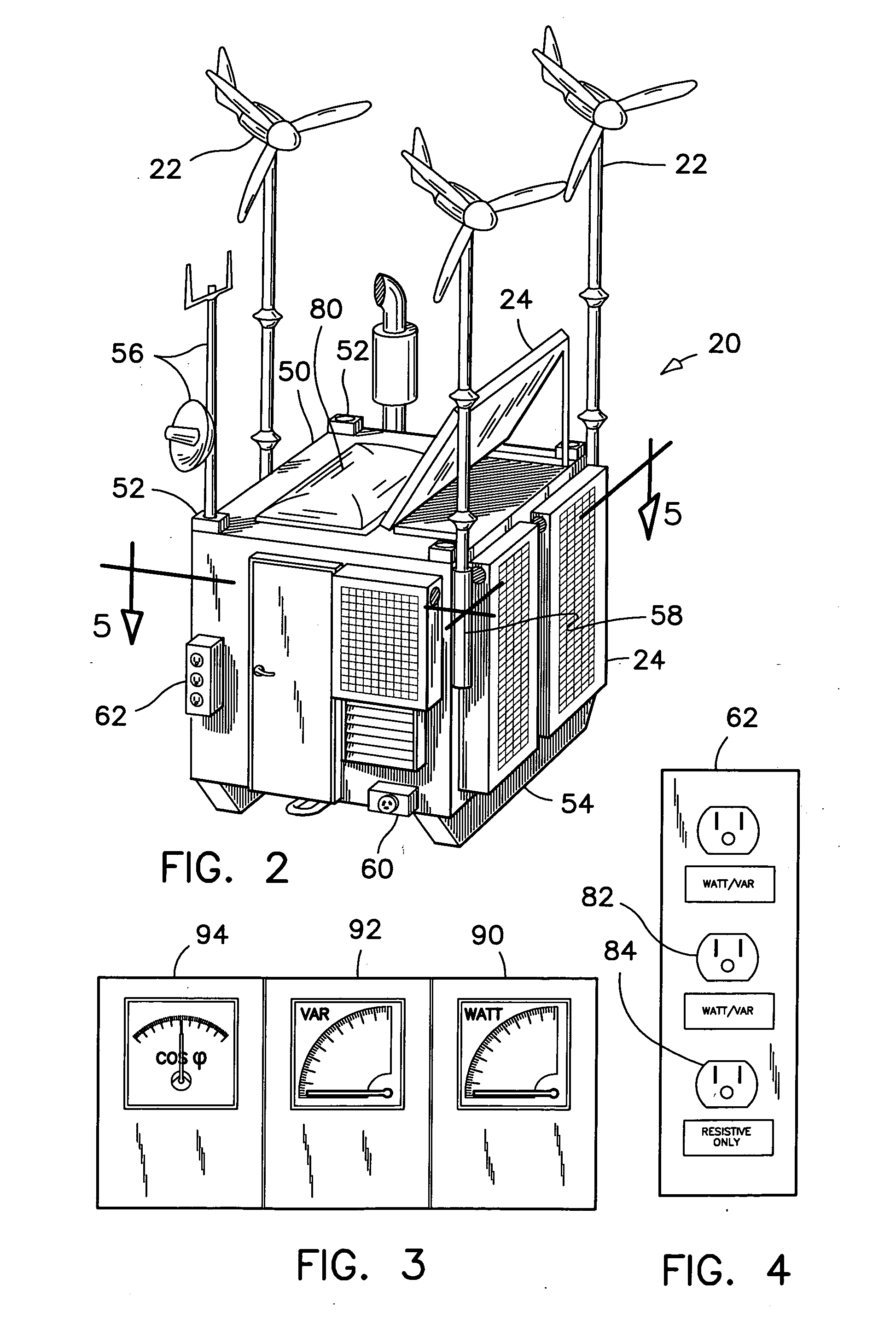
[0030]Referring firstly to FIGS. 1 and 2, there are disclosed therein the systems and devices related to the operation of the preferred multi-source renewable energy station, hereinafter also referred to as the preferred energy station 20. The preferred energy station 20 combines solar, wind and other renewable energy sources for generating electrical power and making available this electrical power to a user in an off-grid environment.

[0031]The preferred energy station 20 comprises a cubical enclosure 20′ for housing all electrical components and controls, and for providing a compact self-standing structure for supporting three wind turbines 22 and several solar panels 24. This preferred energy station 20 also includes electronic instrumentation, switching and controls equipment, a bank of batteries 26, converters 28, and a gas / diesel engine-generator 30, in order to generate stable electric power for reliable use in an off-grid environment. It will be appreciated that the expressi...


PUM


Abstract

The renewable energy station comprising: a housing containing a main central controller and an electrical power distribution center connected to this main central controller. The station comprises wind turbines solar panels, batteries, and a gas / diesel engine-generator. Loads are connected to the electrical power distribution center. The wind turbines and the solar panels are grouped into a plurality of generating cells wherein each generating cell comprises at least one wind turbine and at least one solar panel. The main central controller and the electrical distribution center jointly have switching and control equipment therein for selectively connecting and disconnecting each of the loads to and from the electrical power distribution center. Reactive-type loads are given priority over resistive-type loads. The heat from the gas / diesel engine-generator is used to melt snow and ice from the solar panels. Tandem connection of two stations is done via an inlet receptacle on each station.

Description

[0001]The present patent application claims the benefit of U.S. Provisional Application No. 61 / 996,181, filed May 1, 2014.FIELD OF THE INVENTION[0002]This invention pertains to renewable energy generators. More particularly, it pertains to systems for improving the efficiency of a renewable energy station.BACKGROUND OF THE INVENTION[0003]Renewable energy is a natural option for providing electrical power to users in an off-grid environment. Working with renewable energy sources, however, is not free of risks and challenges. For example solar panels can become frosted or ice-covered in cold climate regions. Wind turbines are moving machines and need to be inspected and maintained. But most of all, renewable energy sources are intermittent and cannot be relied upon when the customer needs a stable and reliable electrical power supply.[0004]The management of renewable energy sources requires relatively complex electronic equipment. The main challenge consists of reducing the risks of a...

Claims


Application Information

Patent Timeline
IPC IPC(8): H02J4/00G05B15/02
CPCH02J4/00Y10T307/367G05B15/02H02J3/18Y02B70/3225Y02E40/30Y04S20/222H02J2300/10H02J2300/20H02J3/381Y02E10/76H02J2310/60H02J3/144H02J2300/24H02J3/388H02J3/40H02J2300/28Y02E10/56
Inventor ILINCA, ADRIANCHAUMEL, JEAN-LOUIS
Owner ILINCA ADRIAN
Learn More